
Compact low RCS ultra-wide bandwidth conical monopole antenna

a conical monopole antenna, ultra-wide bandwidth technology, applied in the direction of individual energised antenna arrays, resonant antennas, elongated active element feeds, etc., can solve the problems of insufficient gain across the entire bandwidth of the conical monopole antenna, preventing its use as an antenna, and unfavorable detection of dipole patterns. , to achieve the effect of low cost and high gain

Inactive Publication Date: 2006-02-28
BAE SYST INFORMATION & ELECTRONICS SYST INTEGRATION INC
View PDF14 Cites 41 Cited by
  • Summary
  • Abstract
  • Description
  • Claims
  • Application Information

AI Technical Summary

Benefits of technology

[0018]The monocone antenna has application in missile threat detection systems to protect aircraft against incoming missiles without having to reconfigure a wing or use conformal wing-glove protection, with the omnidirectional coverage of the antenna eliminating the problems with the narrow lobe of notch-type antennas used in the past. The small monocones are unobtrusive when mounted to a fuselage or wing and may be utilized as IFF C-band antennas for identification of friend or foe or as instrument landing systems antennas. When these antennas are spaced along a wing one can obtain long baseline interferometry so as to obtain a rough estimate of the direction of a microwave source, with the antennas acting as point sources for each location along the wing. Additionally, the monocones have an up to 100-watt CW rating and are extremely low cost, since neither the wings nor fuselage of the aircraft need be specially configured to house the antennas. As a result, the antennas can be sprinkled liberally over the aircraft, with the antennas being ultra-wide bandwidth, small, high gain, omnidirectional antennas.

Problems solved by technology

The problems with the slot antennas are, first and foremost, that the aircraft wing or fuselage must be specially configured or formed so as to house or carry the slot antenna.
Moreover, when Vivaldi notch antennas are utilized, at the higher frequencies these antennas are highly directional with a very narrow antenna lobe that in some cases precludes their use as an antenna to detect missiles coming in from all directions.
Moreover, they do not provide adequate gain across their entire bandwidth.
By way of further background, if one utilizes a double cone or discone, the radiation pattern for these antennas is a dipole pattern which is not useful in detecting missiles coming up from directly beneath an aircraft because the missile will be in an antenna null.
It is noted in this patent that when these conical antennas are arrayed, their radiation patterns tend to interfere with each other, which complicates direction finding processes.

Method used


Image

  • Compact low RCS ultra-wide bandwidth conical monopole antenna
  • Compact low RCS ultra-wide bandwidth conical monopole antenna
  • Compact low RCS ultra-wide bandwidth conical monopole antenna

Examples


Embodiment Construction

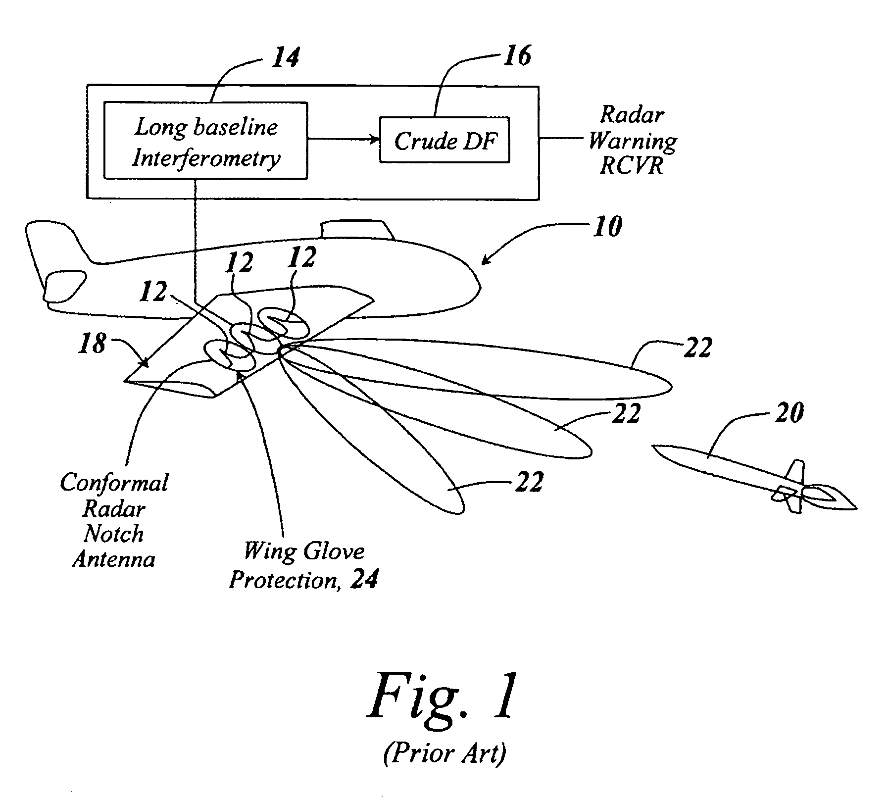
[0033]Referring now to FIG. 1, an aircraft 10 in the past has been provided with Vivaldi notch or slot antennas here illustrated at 12 which are coupled to a long-base interferometry detection unit 14 which outputs a crude direction finding output at 16 indicating the direction of a source of microwave energy impinging on wing 18.

[0034]The microwave energy can come from an on-board radar for an incoming missile 20 which utilizes its radar to search out a target aircraft when the missile is at some distance from the aircraft. It is the purpose of the long baseline interferometric system to determine the direction from which the missile is coming.

[0035]Note that with Vivaldi notch antennas, used primarily because of their ultra-wide bandwidth, their main lobes 22 are highly directional, especially at the higher frequencies, making omnidirectional use impractical.

[0036]Moreover, in terms of mounting the notch or slot antennas to the wing of an aircraft, it will be appreciated that the ...


PUM


Abstract

A low radar cross-section monocone antenna is provided with an ultra-wide bandwidth in the microwave region of the electromagnetic spectrum running from 1 gigahertz to 18 gigahertz by decreasing the low frequency cutoff through enlarging the overall dimensions of the cone while at the same time maintaining the base diameter of the apex of the cone to the initially-set dimension that establishes the high frequency cutoff of the antenna. The apex of this cone that serves as its feed point has a base diameter that results in the wide bandwidth, with the monocone antenna having a 5 dBi gain and omnidirectional coverage.

Description

FIELD OF THE INVENTION[0001]This invention relates to ultra-wide band microwave antennas and more particularly to the utilization of a monocone configured to have high gain with an 18:1 frequency ratio.BACKGROUND OF THE INVENTION[0002]Typical aircraft-mounted microwave antennas utilized, for instance, for detecting incoming missile radars, have in large part been configured as slot antennas within the wing or fuselage of an aircraft; or have involved so-called Vivaldi notch antennas used primarily for their ultra-wide bandwidth.[0003]The problems with the slot antennas are, first and foremost, that the aircraft wing or fuselage must be specially configured or formed so as to house or carry the slot antenna. Oftentimes these antennas are spaced along the edge of the wing and the wing is provided with a so-called wing glove to protect the antennas from environmental erosion, including rain and particle erosion. The wing gloves are also utilized to maintain the appropriate airflow acro...

Claims


Application Information

Patent Timeline
Patent Type & Authority Patents(United States)
IPC IPC(8): H01Q1/28H01Q13/00H01QH01Q1/02H01Q1/36H01Q9/40H01Q21/08
CPCH01Q1/28H01Q21/08H01Q9/40H01Q1/36
Inventor MARSAN, LYNN A.URBANIK, EDWARD A.
Owner BAE SYST INFORMATION & ELECTRONICS SYST INTEGRATION INC
Learn More