Dermoscopy epiluminescence device employing cross and parallel polarization

Active Publication Date: 2006-02-28
DERMLITE LLC
View PDF27 Cites 151 Cited by
  • Summary
  • Abstract
  • Description
  • Claims
  • Application Information

AI Technical Summary

Benefits of technology

[0023]A viewing polarizer is also provided positioned in the housing in line with viewing corridor of the optical lens. The viewing polarizer filters light reflected back from the skin and is cross-polarized relative to said first polarizer and is parallel-polarized relative to said second illumination source. The cross-polarization aids the examiner in viewing deeper structures of the skin while the parallel polarization aids in viewing the topography of the skin.
[0024]In a second embodiment of the invention, the ring of diodes that surround the lens incorporate alternating light wavelengths of differing colors. In operation, a user initiates the first light circuit by operating the first ON mode of the housing switch to light every other diode of a first color. The user then can initiate the second ON mode to light every other diode of a second color. Finally the user can initiate a third ON mode and light both sets of diodes to emit bo

Problems solved by technology

While oil-immersion has proved to be an excellent method of epiluminescence imaging of the skin, demonstrating improved sensitivity for melanoma detection, it is messy and time consuming for the physician.
Also, the oil-immersion of the Dermatoscope has been found to be less effective for BCC and SCC imaging.
The pressure created by the compression of the glass faceplate causes blanching of blood vessels in the skin resulting in reduced capability of the Dermatoscope for imaging the telangiectesia that is often associated with BCC or other malignent lesions.
In light of many of the difficulties associated with prior dermoscopy systems, a simple and cost-effective diagnostic systems remained unavailable for general dermatologists to use on a routine clinical basis.
Although, the DermLite® pro

Method used


Image

  • Dermoscopy epiluminescence device employing cross and parallel polarization
  • Dermoscopy epiluminescence device employing cross and parallel polarization
  • Dermoscopy epiluminescence device employing cross and parallel polarization

Examples


Embodiment Construction

[0033]The detailed description as set forth below in connection with the appended drawings is intended as a description of the presently preferred embodiments of the present invention, and does not represent the only embodiment of the present invention. It is understood that various modifications to the invention may be comprised by different embodiments and are also encompassed within the spirit and scope of the present invention.

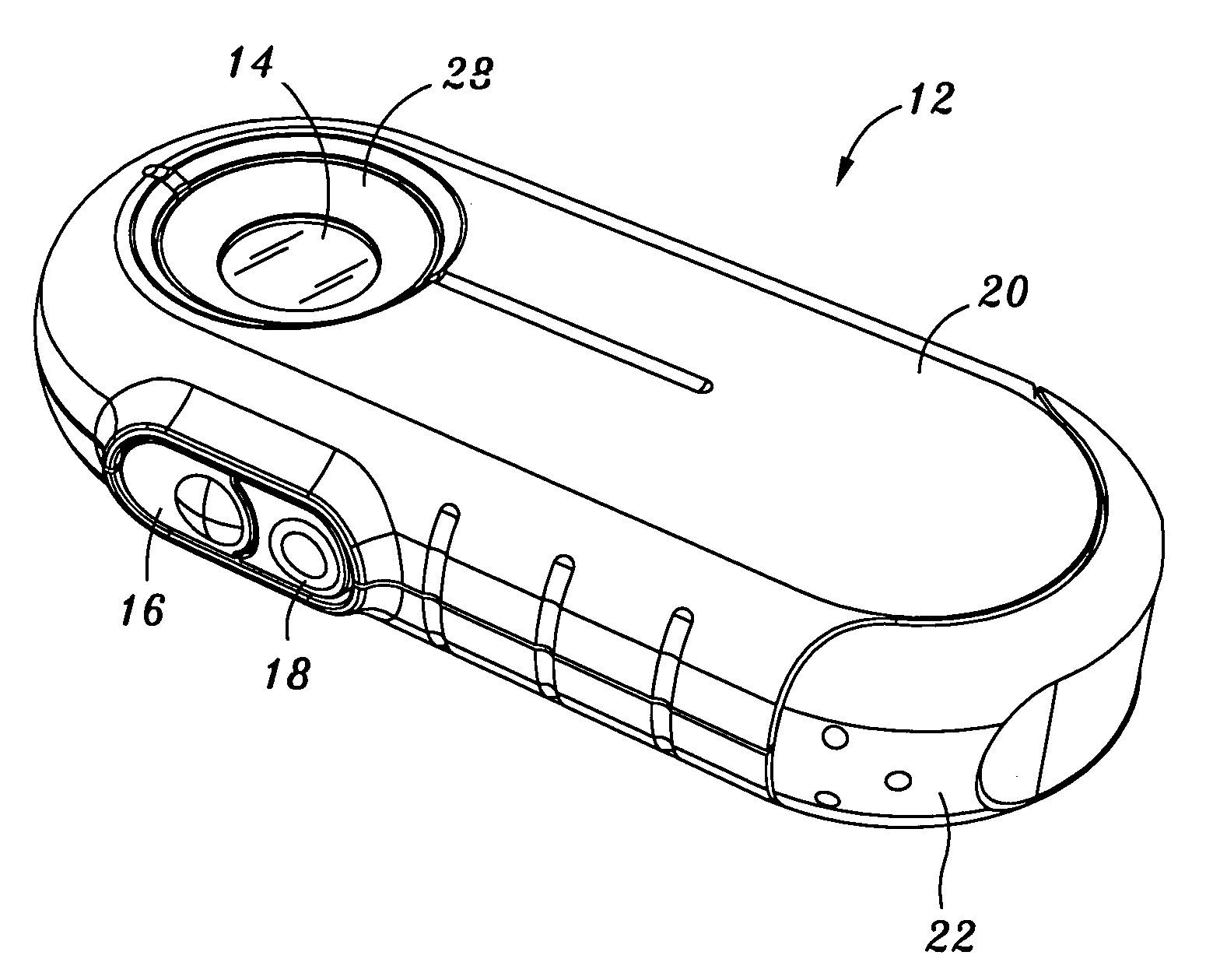
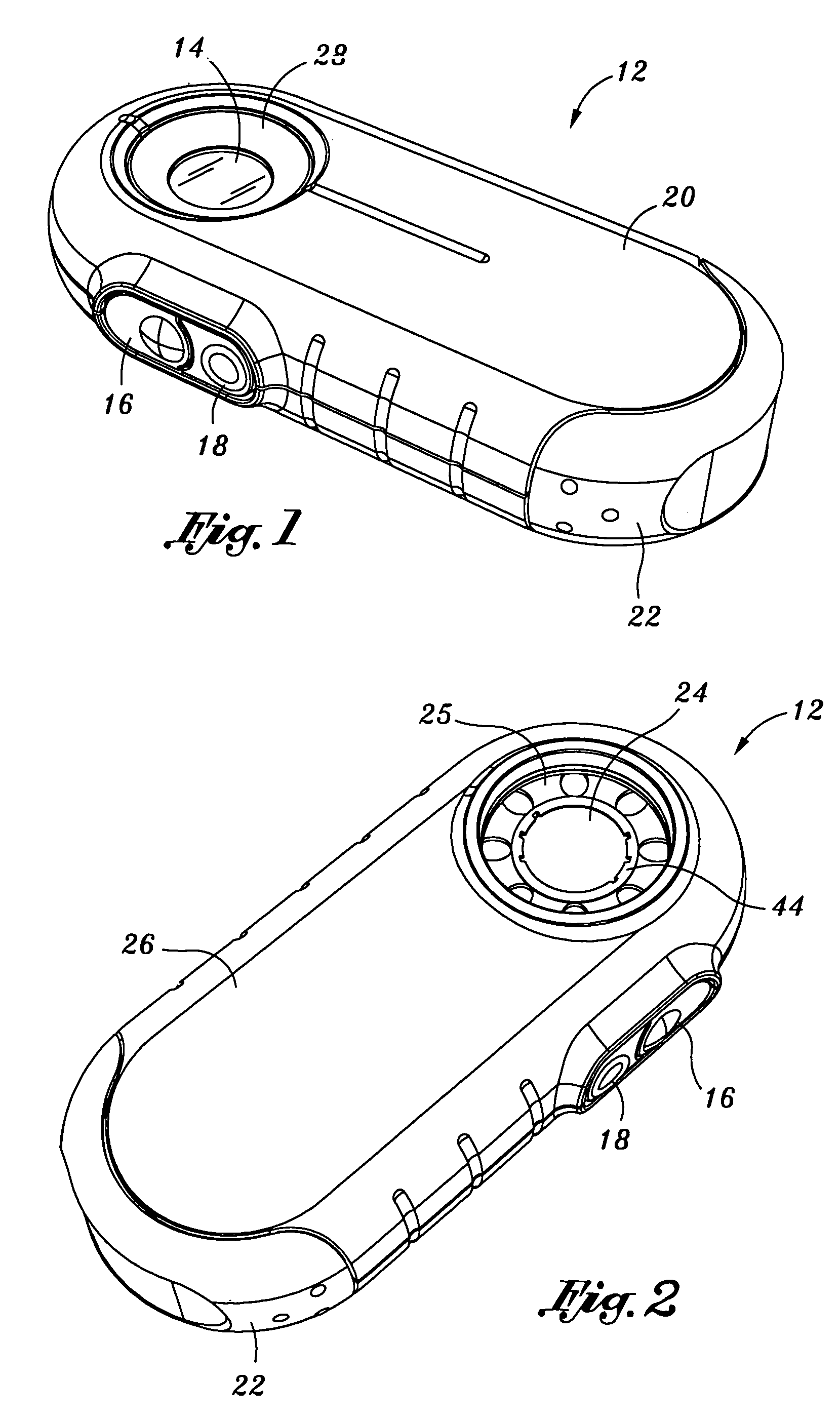
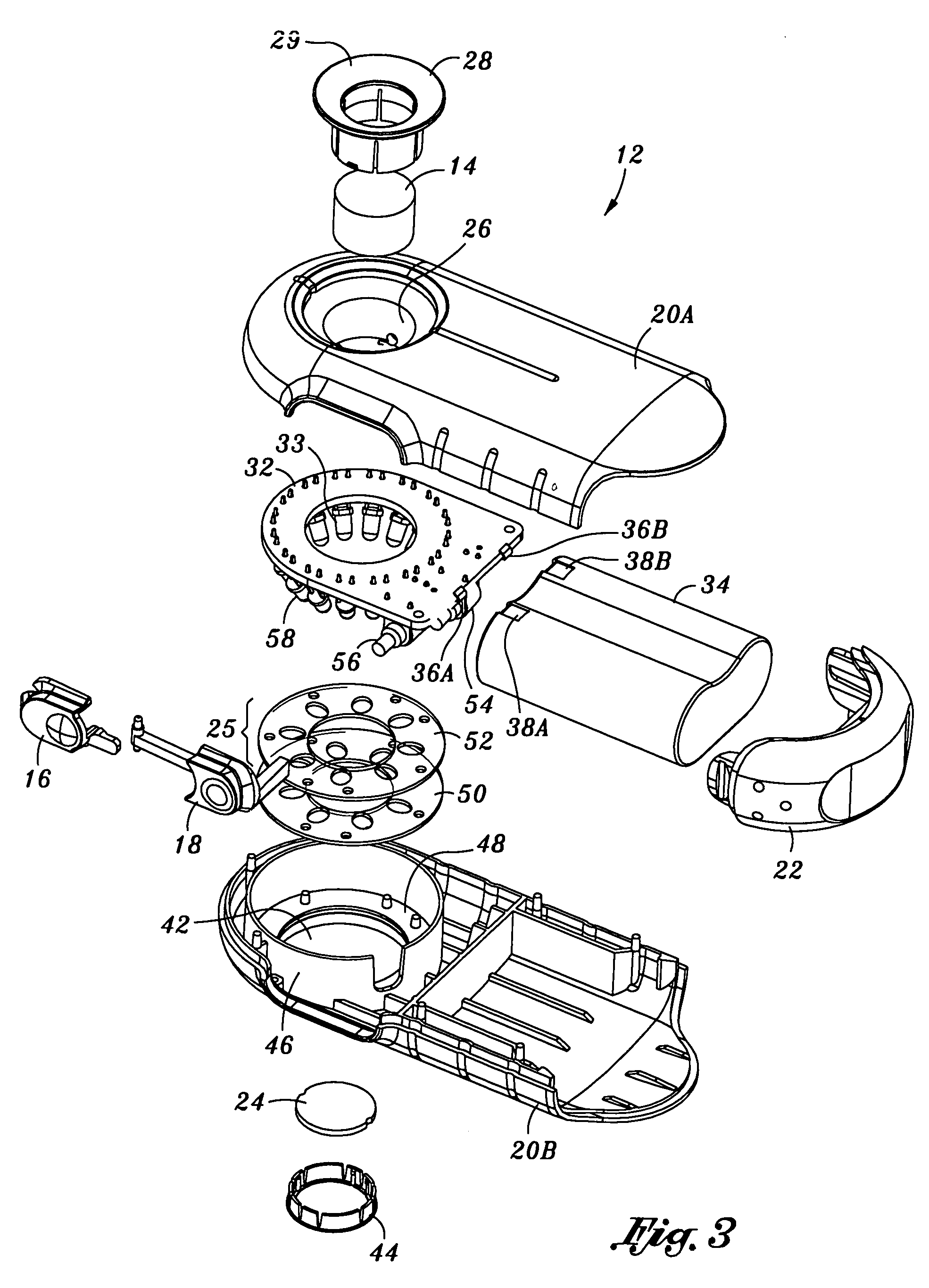
[0034]Referring particularly to FIGS. 1 and 2, there are shown a top and bottom perspective views, respectively, of the dermoscopy epiluminescence device 12 of the present invention. The device 12 is lightweight and compact, and can easily fit within the shirt pocket of a user. The outer structure of the device 12 can be utilized in association with the first embodiment (FIGS. 3–5), the second embodiment (FIG. 6) and third embodiment (FIG. 7). The exterior appearance of the device for each of the first, second and third embodiments would be identical as sh...


PUM


Abstract

The present invention is a hand held dermoscopy epiluminescense device with a magnification lens and an associated ring of luminous diodes powered by an on board battery. Every other diode in the ring operates as first and second light sources. The even diodes are filtered by a first polarization ring and the odd diodes are filtered by a second polarization ring. Each polarization ring has an open center for the lens and openings sized and positioned to correspond to the even or odd diodes to only filter one set. A viewing polarizer is provided and is cross-polarized relative to the first polarization ring and is parallel-polarized with the second polarization ring. A three way switch which provides on demand cross-polarized, parallel-polarized and a combination thereof for epiluminescence. A second embodiment provides even diodes of a first color and odd diodes of a second color. A third embodiment employs the alternating colored diodes of the second embodiment as well as the cross and parallel polarization of the light from the diodes as found in the first embodiment.

Description

CROSS-REFERENCE TO RELATED APPLICATIONS[0001](Not Applicable)STATEMENT RE: FEDERALLY SPONSORED RESEARCH / DEVELOPMENT[0002](Not Applicable)FIELD OF THE INVENTION[0003]The present invention relates generally to an epiluminescence device used in dermoscopy. More particularly, the invention comprises an improved apparatus for illuminating the skin for medical examination by providing cross-polarized and parallel-polarized light to aid in viewing internal structures as well as the skin surface.BACKGROUND OF THE INVENTION[0004]Dermoscopy is the term used to describe methods of imaging skin lesions. Skin is the largest organ in the body and it is the most easily accessible organ for external optical imaging. For early detection of cancers, it is important that the skin be medically examined for lesions.[0005]With over forty (40%) percent of the cancers occurring on the skin (American Cancer Society Statistics 2001, Perelman 1995), and incidence of skin cancer increasing each year, tools and...

Claims


Application Information

Patent Timeline
IPC IPC(8): G01J4/00A61B5/103G01N21/64
CPCA61B5/0059A61B5/444G01N21/6447G01N21/6445A61B5/445G01N21/6458
Inventor MULLANI, NIZAR A.
Owner DERMLITE LLC
Why Eureka
Try Eureka