Micro-optics for article identification

a micro-optic and article technology, applied in the field of optical security devices, can solve the problems of limited security provided by embossed holograms, inability to prevent holographic copying methods, and easy counterfeiting, and achieve the effect of reducing the quality of reproduction

Inactive Publication Date: 2006-02-28
PRINTPACK ILLINOIS
View PDF6 Cites 76 Cited by
  • Summary
  • Abstract
  • Description
  • Claims
  • Application Information

AI Technical Summary

Benefits of technology

[0011]Still another aspect of the present invention includes a plurality of tapered structures wherein said tapered structures are covered with a reflective material such that light is reflected among the tapered structures until substantially all of the reflected light has been absorbed. These micro-optics have the effect of producing a black zone or cone of darkness that can be used with or without reflective optics to form an image. The reflective optics can include a reflective material, for example a met

Problems solved by technology

The security provided by embossed holograms is limited by their low surface relief, typically 0.25 micron, which makes them susceptible to counterfeiting: stripping the hologram from the substrate exposes the complete holographic microstructure which can be easily used to create counterfeit tooling.
Limited p

Method used


Image

  • Micro-optics for article identification
  • Micro-optics for article identification
  • Micro-optics for article identification

Examples


first embodiment

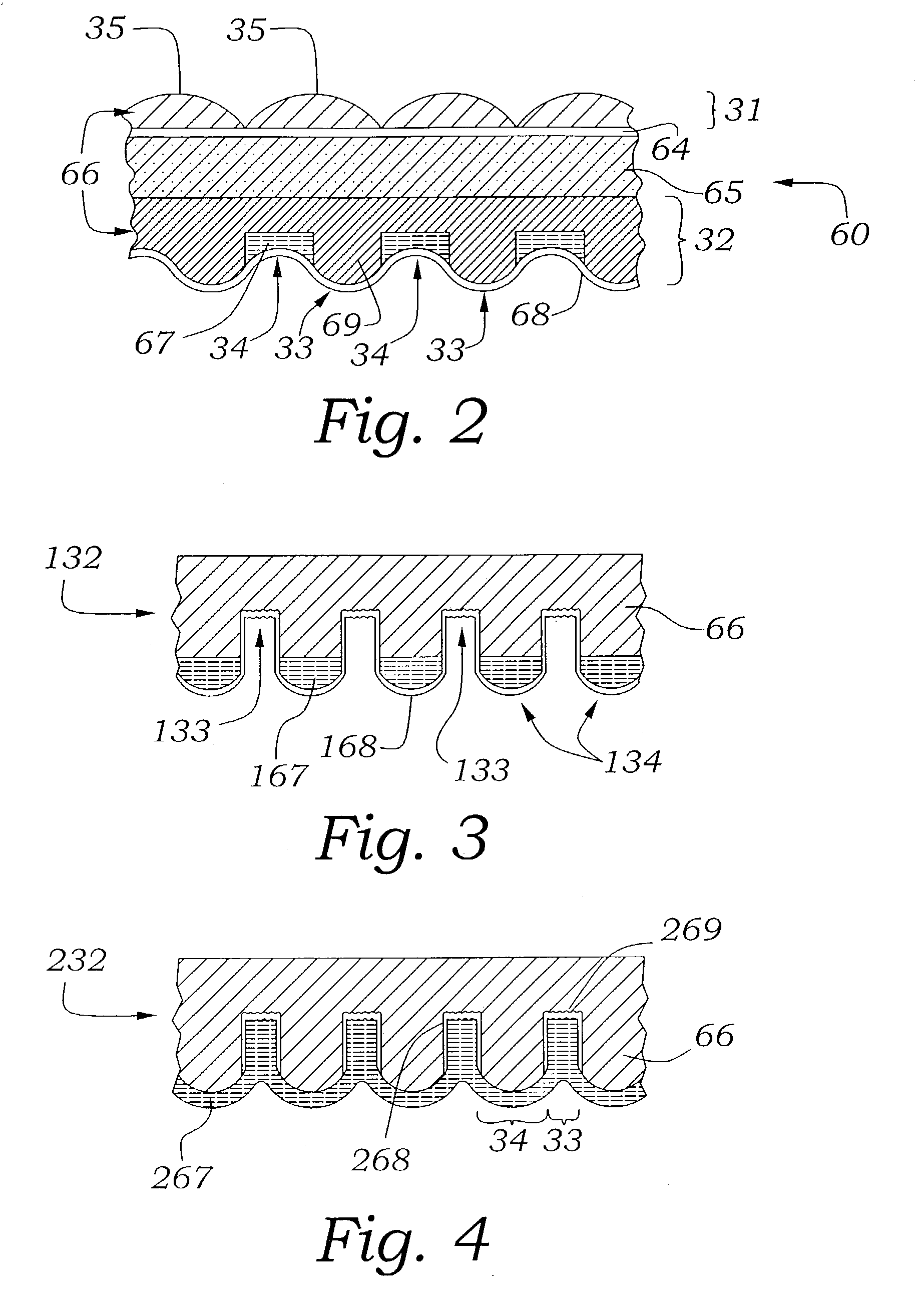
[0089]While FIG. 2 shows one preferred embodiment of the invention, there are numerous alternative ways of designing the light control optics, as shown in FIGS. 3–5. FIG. 3 shows an alternative design in which the geometric pattern of the light control optics 132 is the reverse of that shown in the preferred embodiment. In other words, the bright zones in this embodiment are located in those areas where the dark zones were located in the In this embodiment, the dark zones 134 are formed in the recessed notches created in the reflective substrate 168 with an opaque material 167 and the bright zones 133 are formed in between. The relative positions of the dark zones and the bright zones along the light control optics are reversed from that of the embodiment shown in FIG. 2. In the embodiment of FIG. 3, the present invention will function in a light reflective mode due to the presence of the reflective layer 168.

[0090]FIG. 4 shows a second alternative design for the light control opti...

second embodiment

[0118]FIGS. 15a and 15b illustrate a second embodiment for interleaving the images in emulsion 830. The emulsion 830 is exposed to the right image through mask 840. The emulsion 830 can be exposed through contact printing or by projection with an enlarger (not shown). The mask 840 is then shifted to cover the right image strips and the emulsion is exposed to the left image. The emulsion is then developed, thereby producing interleaved left and right image strips in the emulsion, as shown in FIG. 15b. Although only left and right image strips are shown in FIGS. 13–15b, these embodiments are not limited to any particular number of images. Left and right images are shown merely for ease of illustration. The number of images which can be interleaved in emulsion 830 is limited only by the limitations of conventional techniques used for interleaving images in an emulsion.

[0119]One of the advantages of the invention described with regard to FIGS. 13–15b is that conventional photoprocessing...


PUM


Abstract

The present invention provides methods and compositions for authentication of articles and counterfeit deterrence using non-holographic micro-optics and microstructures having a surface relief greater than a few microns. Embodiments of the present invention disclose a range of distinctive optical effects obtained from micro-optic systems incorporating micro lenses, non-imaging collectors, prisms, wave guides, mirrors, gratings, structural interference filters, and photonic crystal microstructures.

Description

CROSS REFERENCE TO RELATED APPLICATIONS[0001]This application claims priority to and benefit of both U.S. provisional application No. 60 / 351,853 filed on Jan. 24, 2002, and to U.S. provisional application No. 60 / 352,000 filed on Jan. 24, 2002, both of which are incorporated by reference in their entirety.BACKGROUND OF THE INVENTION[0002]1. Field of the Invention[0003]The present invention relates generally to optical security devices, more particularly to optical security devices and identification for articles, and particularly, documents and financial instruments.[0004]2. Related Art[0005]Surface relief holograms, also known as embossed holograms, have been utilized to authenticate financial instruments and high value products for many years. The security provided by embossed holograms is limited by their low surface relief, typically 0.25 micron, which makes them susceptible to counterfeiting: stripping the hologram from the substrate exposes the complete holographic microstructu...

Claims


Application Information

Patent Timeline
IPC IPC(8): G02B27/10G09C3/00B42D15/00G02B3/00G02B5/00G02B5/08G02B5/18G02B5/28G02B5/32G02B30/27G07D7/12G09C5/00
CPCB82Y20/00G02B5/1861G02B3/0012G02B3/0031G02B3/0043G02B3/0068G02B5/003G02B5/08G02B5/1814G02B5/28G02B5/285G02B5/287G02B27/2214G07D7/121G07D7/2058B42D25/29G02B1/005G02B5/32B42D25/328Y10T428/24802Y10T428/24917G07D7/206G03H1/0244G02B30/27
Inventor STEENBLIK, RICHARD A.HURT, MARK J.KNOTTS, MICHAEL E.
Owner PRINTPACK ILLINOIS
Why Eureka
Try Eureka