Computed tomography apparatus and program

a tomography and computed tomography technology, applied in tomography, instruments, nuclear engineering, etc., can solve the problems of large computation, insatiable use of medical image diagnostic equipment, and inability to apply actual discrete data degradation, etc., to achieve high accuracy, high speed, and high approximation accuracy

Active Publication Date: 2006-02-28
TOSHIBA MEDICAL SYST CORP
View PDF9 Cites 13 Cited by
  • Summary
  • Abstract
  • Description
  • Claims
  • Application Information

AI Technical Summary

Benefits of technology

[0025]As described above, according to the present invention, it is possible to provide an image reconstruction method which is practicable and affords a high precision, and also a three-dimensional CT system which has the functions of the image reconstruction method. More specifically, in a helical oblique section reconstruction method in helical CT having a multirow detector, an image can be obtained with a higher approximation precision than in the prior-art method, and a three-dimensional image can be acquired at high speed and with fewer artifacts than in the prior-art method. Thus, the secondary advantages are expected to be brought forth that the resolution and definition of a three-dimensional CT image are enhanced, and that the distortion of the signal value of the CT image becomes small.

Problems solved by technology

Approaches to the developments of image reconstruction algorithms having heretofore been made, however, have had the problem that, although the exact solution is concerned, the quantity of computations is large, so degradation ascribable to interpolation processing is liable to occur in case of employing actual discrete data.
There has also been the problem that, since the range of data necessary for obtaining a certain slice image is wide, the data are easily influenced by the peripheral tissues of a subject and the temporal fluctuation thereof, so they are not satisfactory for use in a medical image diagnostic equipment.
Nevertheless, it is an actual situation that the precisions of approximations by techniques hitherto proposed cannot be said satisfactory, and that artifacts remain yet.

Method used


Image

  • Computed tomography apparatus and program
  • Computed tomography apparatus and program
  • Computed tomography apparatus and program

Examples


first embodiment

[First Embodiment]

[0120]I. Necessary Conditions

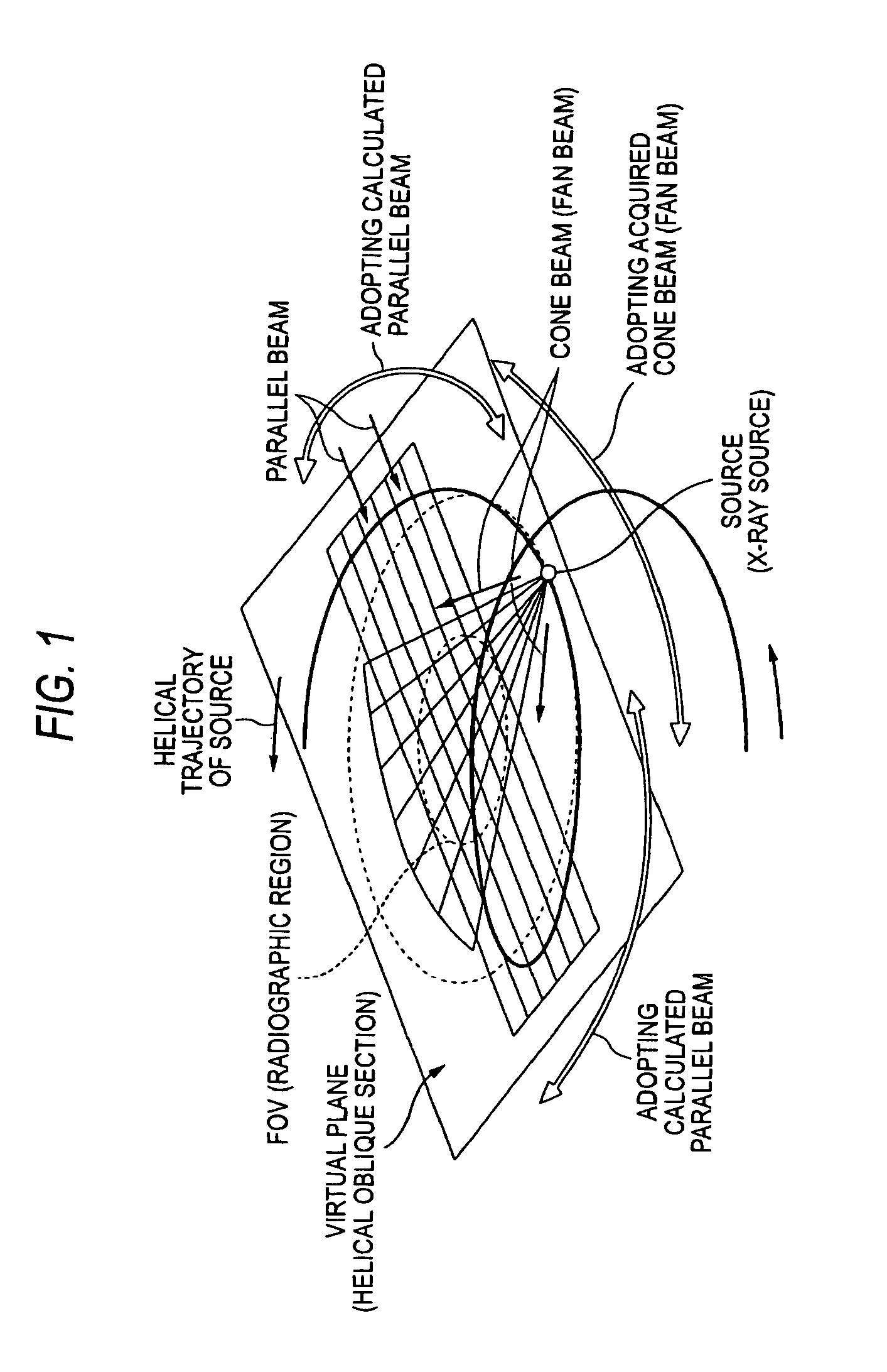
[0121]In order to complete beams necessary for image creation by employing acquired cone beam data and converted parallel beam data, the angle κ of a virtual oblique section and the angle κ′ of the direction of the line of sight for parallel beams must be carefully set. The foregoing example corresponds to the case of setting κ=κ′ at 9.04 degrees. Conditions to be satisfied are as arranged below.

[0122](1) A certain wide range is covered as the acquired cone beam data hold a suitable approximation precision even outside the vicinity of that direction (θ=0) of a source in which an oblique section has been set.

[0123](2) A certain wide range is covered as calculated converted parallel beams hold a suitable approximation precision even in directions other than the direction of θ=90 degrees.

[0124](3) When both cone beams and the parallel beams are combined, all beams required for creating the image of the oblique section can be obtained.

[0125...

second embodiment

[Second Embodiment]

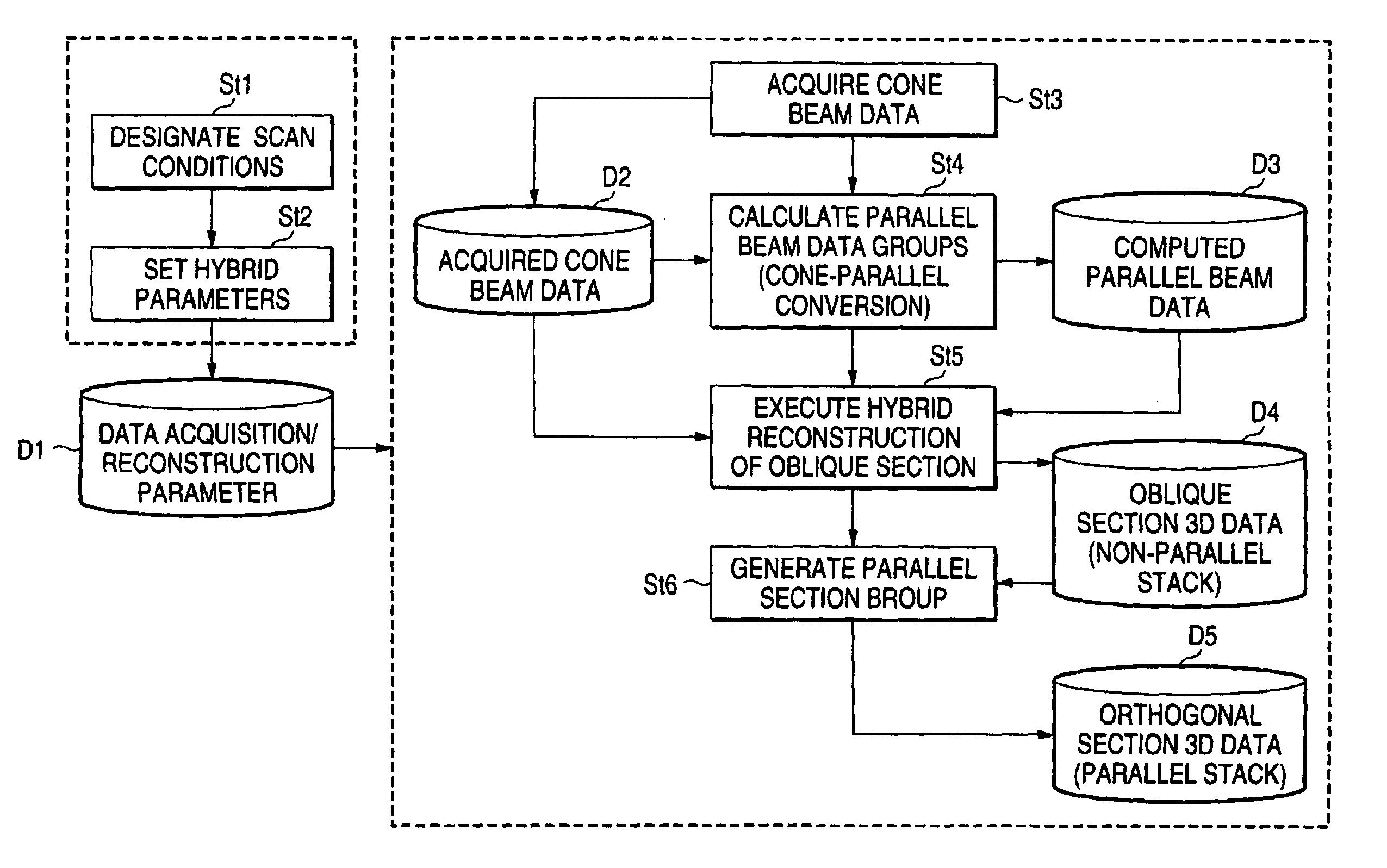
[0160]Data acquisition, CP conversion processing, the calculations of weighting functions, etc. are the same as in the first embodiment. In the second embodiment, the last image reconstruction portion is different. After fan beam data are multiplied by the weights wf indicated in the first embodiment, ordinary reconstruction is executed using the fan beams. On the other hand, parallel beams after CP conversion are multiplied by the weighting function wp, and parallel beam reconstruction is executed. Regarding directions in which quite no data exist, back projection calculations may well be omitted. The reconstructions concerning the two sorts of data are executed by different calculating algorithms, but both the algorithms afford equivalent calculations. Accordingly, a correct image can be obtained even when intermediate images, in a sense, are created for the respective sorts of data and are thereafter added. The flow of the processing in this embodiment is as sh...

third embodiment

[Third Embodiment]

[0163]As commented at the last of the outline preceding the first embodiment, a solution with better approximation is obtained when the tilt angle of parallel beams is changed depending upon the direction of the line of sight.

[0164]Although the single tilt angle is representatively used in the first and second embodiments, a method employing two angles will be described here. More specifically, an example of κ=10.5 degrees and κ′=9.5 degrees and an example of κ=10.5 degrees and κ2′=8 degrees will be explained. Parallel beams calculated in the pair of κ=10.5 degrees and κ′=9.5 degrees correspond to the first embodiment, and data calculated in the pair of κ=10.5 degrees and κ2′=8 degrees form an essential element added thereto. In other words, the method consists in the idea that the latter data are used to compensate for a region which is difficult to be covered with the former data, or a region in which errors are large.

[0165]FIGS. 17A and 17B show the generatable ...


PUM


Abstract

A computed tomography apparatus includes a two-dimensional data acquisition system which acquires projection data of a radiographic region within a subject using a multirow detector, and a hybrid image reconstruction system which reconstructs an image of the radiographic region on the basis of both the projection data and additional data calculated from the projection data. The hybrid image reconstruction system functionally includes a unit for calculating an additional intermediate beam data set, a unit for executing hybrid reconstruction of an oblique section, and a unit for generating a parallel section group. Owing to the construction, there are provided an image reconstruction method which is practicable and which affords a high precision, and a three-dimensional CT system which has the functions of the image reconstruction method.

Description

BACKGROUND OF THE INVENTION[0001]1. Field of the Invention[0002]The present invention relates to a computed tomography (“CT”) apparatus, and more particularly to the image reconstruction method of cone-beam helical CT wherein an X-ray source has a helical trajectory.[0003]2. Description of the Related Art[0004]In recent years, in the field of X-ray CT, basic image reconstruction algorithms have been continuously developed and variously proposed for the practicability of three-dimensional (3D) image display. In, for example, so-called “cone-beam helical CT” wherein an X-ray source has a helical trajectory, a large number of approximate reconstruction techniques have been proposed. The techniques include what is called “TCOT (True COne beam Tomography reconstruction algorithm) method”, a helical oblique section reconstruction method (also called “ASSR method”), etc. These reconstruction techniques obtain approximate solutions to the last, but the existence of an exact solution has rec...

Claims


Application Information

Patent Timeline
Patent Type & Authority Patents(United States)
IPC IPC(8): A61B6/03G06T11/00
CPCG06T11/006A61B6/027Y10S378/901G06T2211/421
Inventor MACHIDA, YOSHIO
Owner TOSHIBA MEDICAL SYST CORP
Why Eureka
Try Eureka