Method for solving finite element models using time slabbing

a time slabbing and finite element technology, applied in the field of methods for modeling physical systems using finite element analysis, can solve the problems of not being able to localize the smaller time steps to a particular physical volume of interest, and more complicated means to model physical systems, so as to achieve the effect of reducing memory usag

Inactive Publication Date: 2006-02-28
LANDMARK GRAPHICS CORP
View PDF67 Cites 42 Cited by
  • Summary
  • Abstract
  • Description
  • Claims
  • Application Information

AI Technical Summary

Benefits of technology

[0006]One or more of the problems outlined above may be solved by the various embodiments of the present invention. Broadly speaking, the invention comprises a method for solving space-time problems involving three-dimensional space by constructing a three-dimensional finite element model, then repeatedly extruding the model in a temporal dimension to form a “time slab” and solving the slab. This method may provide a number of advantages over prior art methods, including decreased memory usage, the ability to refine the spatial mesh from one time slab to another, the ability to adapt the temporal mesh to achieve convergence of a solution for the slab, the ability to perform “checkpointing” of solutions for successive time slabs, and so on.

Problems solved by technology

One of the more complicated means to model physical systems is through the use of finite element analysis.
There was no way to localize the smaller time steps to a particular physical volume of interest or to adapt the three-dimensional spatial model over time.

Method used


Image

  • Method for solving finite element models using time slabbing
  • Method for solving finite element models using time slabbing
  • Method for solving finite element models using time slabbing

Examples


Embodiment Construction

[0020]A preferred embodiment of the invention is described below. It should be noted that this and any other embodiments described below are exemplary and are intended to be illustrative of the invention rather than limiting.

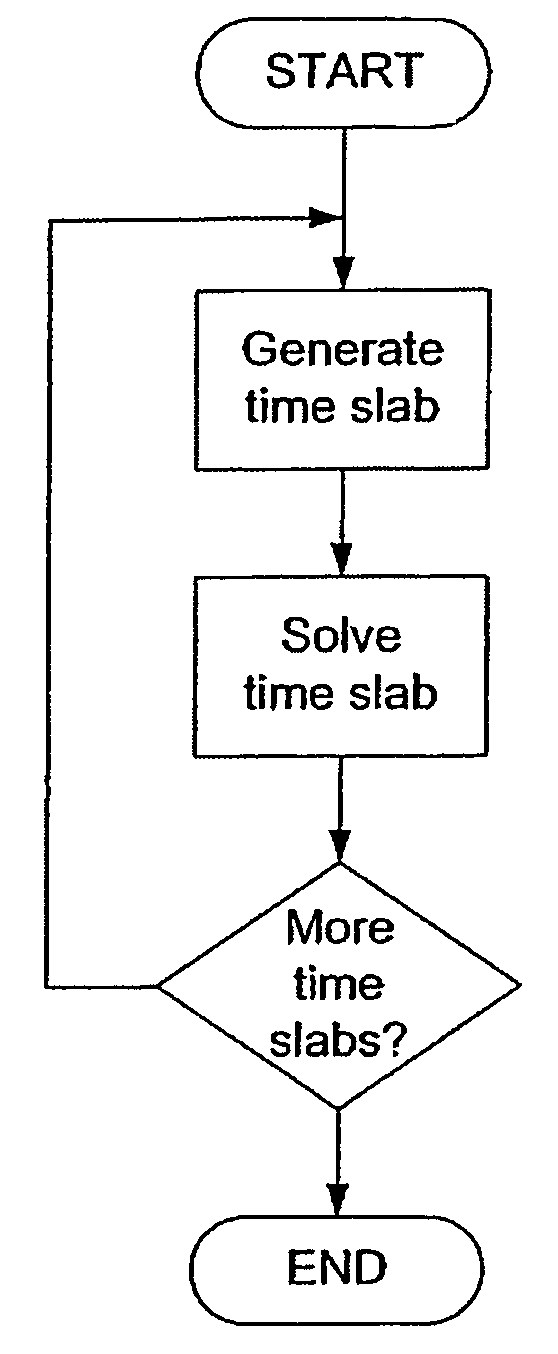
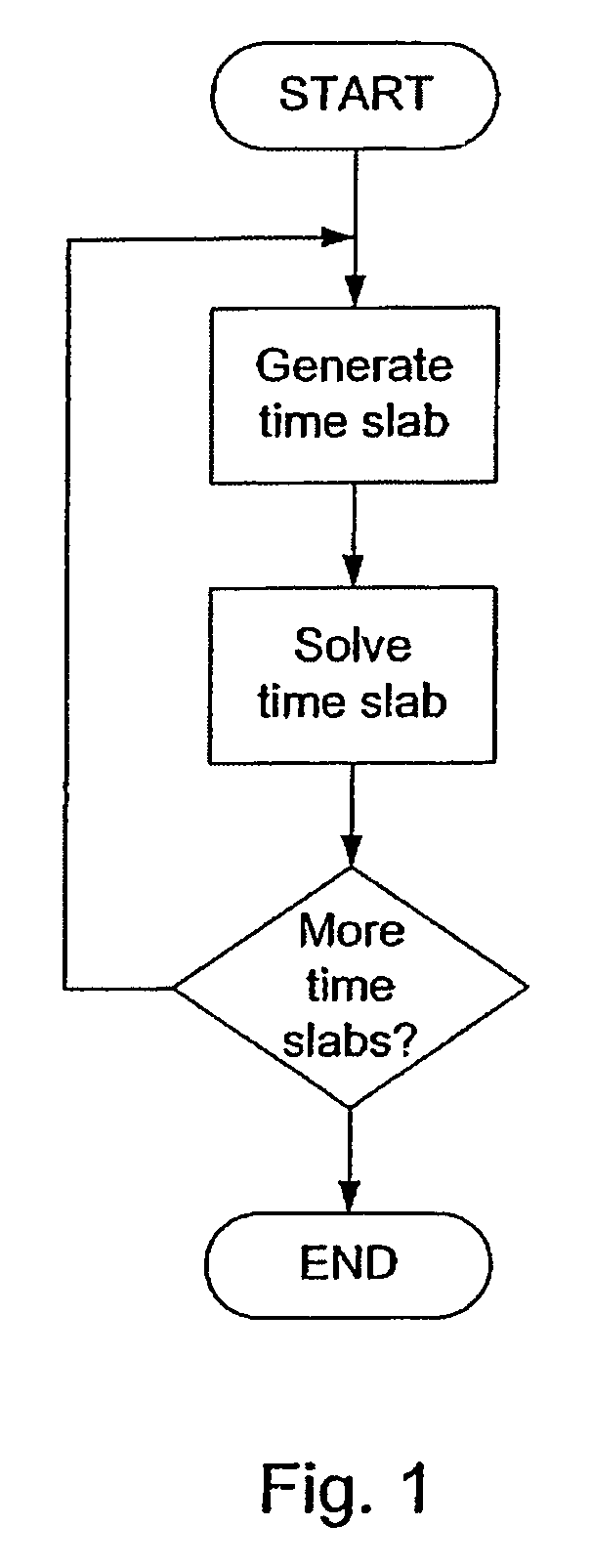
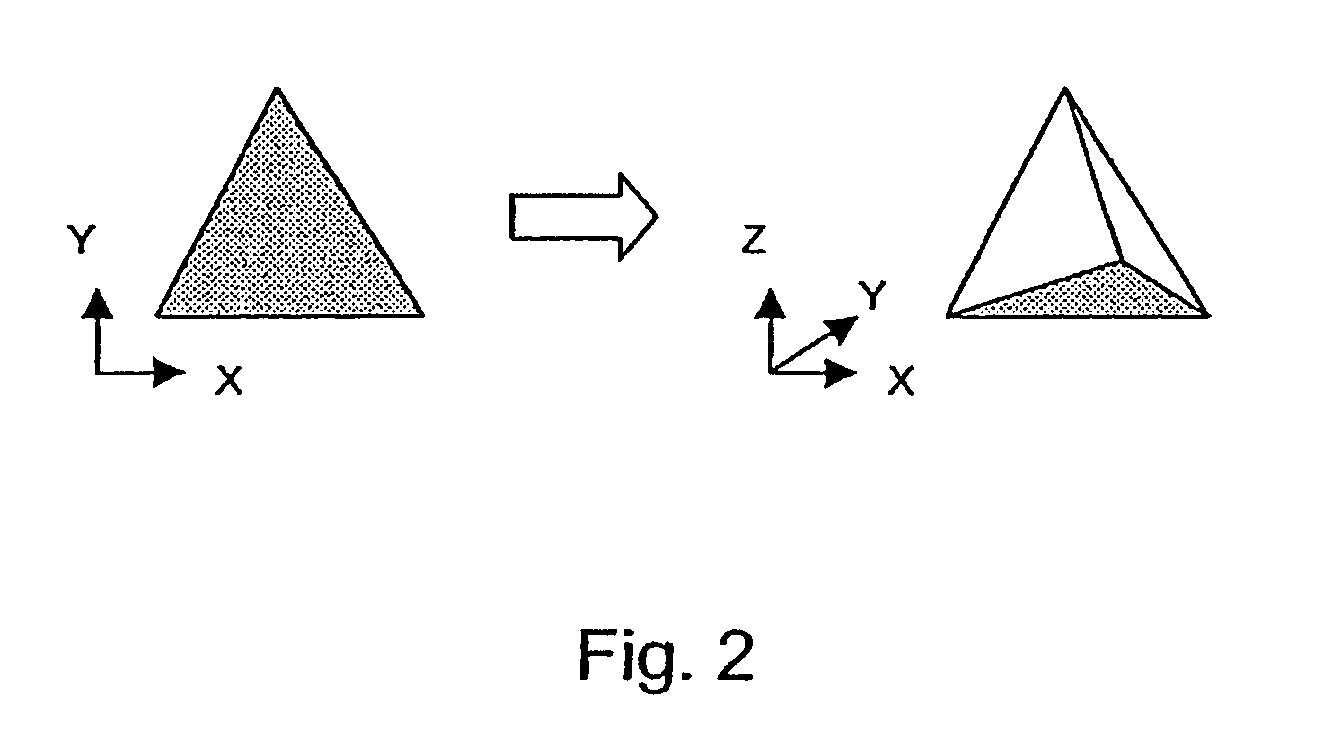
[0021]The present method is particularly well-suited to solving space-time problems involving three-dimensional space. In the prior art, three-dimensional finite element models were solved for a particular point in time. Put another way, the models were three-dimensional instead of four-dimensional. If a solution for the three-dimensional model over time was required, the three-dimensional model was solved for a first time value, then for a second time value, then a third, and so on. Thus, the finite element model was not a four-dimensional model, but was instead a three-dimensional model which was stepped over a given range of time values. The series of three-dimensional solutions to the three-dimensional model could then be combined to construct a four-dimensi...


PUM


Abstract

A method for solving finite element problems in n+1 dimensions by iteratively extruding an n-dimensional finite element mesh in an n+1th dimension to form “slabs” which can be more easily solved within the entire n+1-dimensional problem. In a preferred embodiment, a three-dimensional unstructured finite element mesh representing a physical system is extruded in the time dimension. The four-dimensional prisms formed by the extrusion are divided into simplices, forming the four-dimensional finite element mesh of an individual time slab. Time slabs corresponding to a series of time intervals are sequentially generated and solved. In a preferred embodiment, only a few time slabs are stored in working memory at a time so that a reduced amount of memory (in comparison to conventional methods of solving comparable problems) is required.

Description

RELATED APPLICATIONS[0001]This application claims priority under 35 U.S.C. § 119(e) to U.S. Patent Application No. 60 / 215,697 entitled “Method and System for Oil Reservoir Simulation and Modeling” by Stephen R. Kennon, Kok Thye Lim, Scott A. Canaan, Steven B. Ward, Stuart W. Pond, Jr. and Edward J. Barragy, filed Jun. 29, 2000, which is incorporated by reference as if set forth in its entirety herein.TECHNICAL FIELD OF THE INVENTION[0002]This invention relates generally to methods for modeling physical systems using finite element analysis and, more specifically, to methods for creating finite element models used in simulating geological structures and corresponding fluid flow, especially in hydrocarbon reservoirs.BACKGROUND OF THE INVENTION[0003]Physical systems can be modeled mathematically to simulate their behavior under certain conditions. There are a wide variety of means to model these systems, ranging from the very simplistic to the extremely complicated. One of the more com...

Claims


Application Information

Patent Timeline
Patent Type & Authority Patents(United States)
IPC IPC(8): G06F17/10E21B44/00G01V11/00G06F17/13G06F17/16G06F17/50G06F19/00G06T17/05G06T17/20
CPCG01V11/00G06F17/5004G06T17/20G06T17/05G06F17/5018G06F30/13G06F30/23
Inventor POND, JR., STUART W.BARRAGY, EDWARD J.
Owner LANDMARK GRAPHICS CORP
Why Eureka
Try Eureka