
Urine collection method and apparatus

a collection method and urine technology, applied in the field of urine collection methods and apparatuses, can solve the problems of manual labor and expensive construction, and achieve the effect of simple construction

Inactive Publication Date: 2006-03-07
REXAM HEALTHCARE PACKAGING +1
View PDF14 Cites 39 Cited by
  • Summary
  • Abstract
  • Description
  • Claims
  • Application Information

AI Technical Summary

Benefits of technology

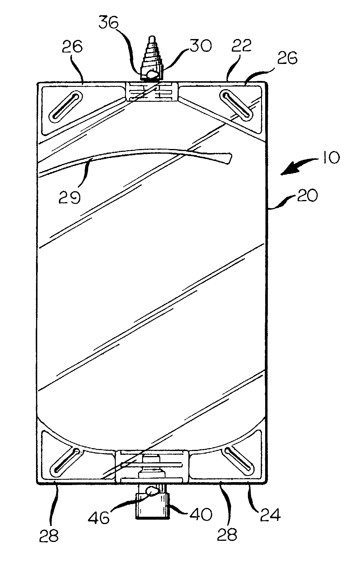
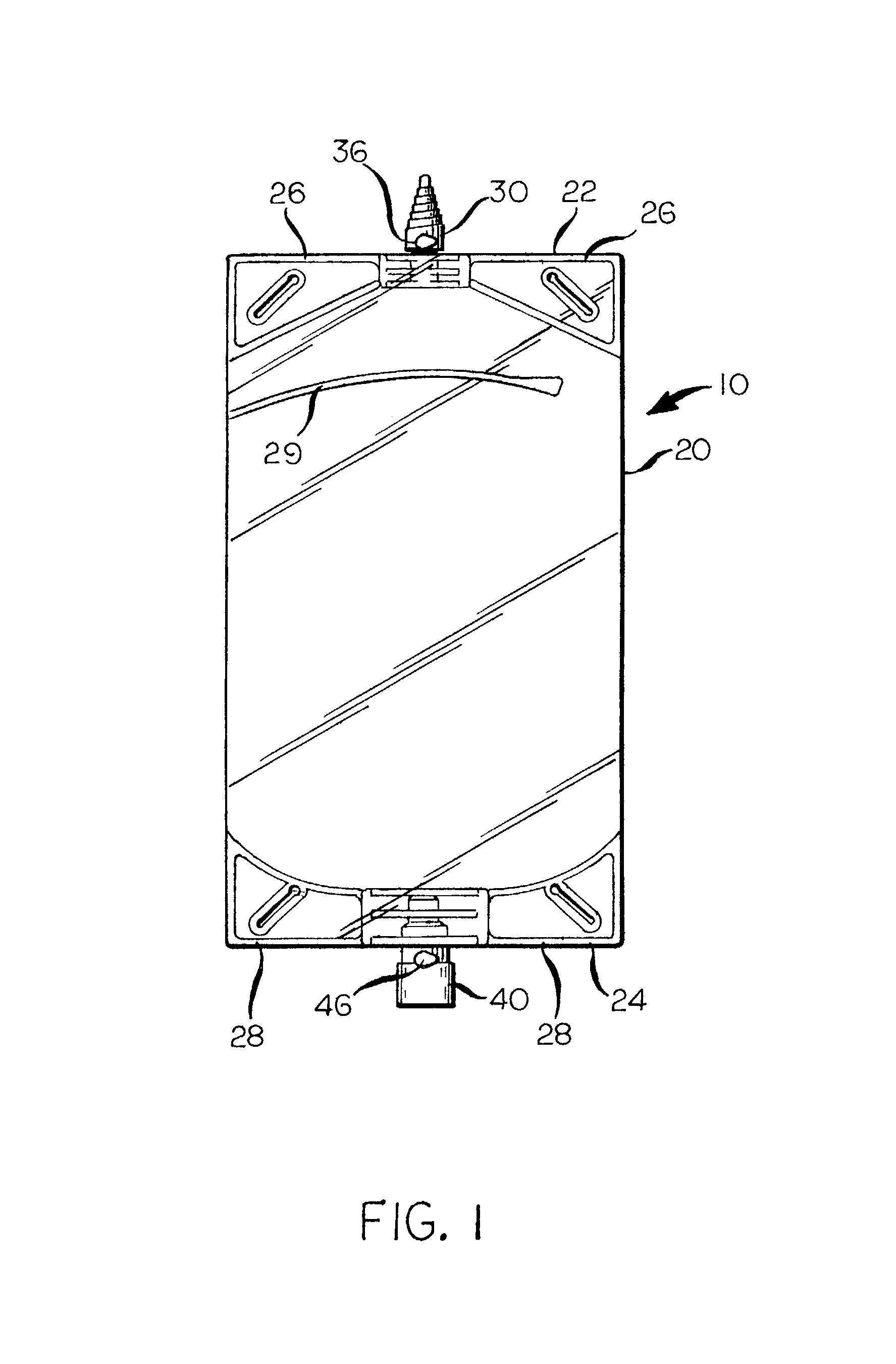
[0007]According to the present invention there is provided a urine collection method and apparatus in which urine is collected in a flexible bag that does not require a separate flutter or one-way valve, either within the bag itself or in an inlet fitment that is secured to the bag, to prevent reverse flow or splashing from the bag into the fitment, or even into an inlet line secured to the fitment. The bag of the urine collection device of the present invention has a heat-staked line extending partly across the bag, at a location near the inlet to the bag and in alignment with the inlet, the free-end(s) of the heat-stake line forming an internal funnel within the bag beyond the free end(s) of the line to allow urine to flow to a lower part of the bag. As the bag fills, its expanding shape closes the funnel, to thereby prevent any reverse flow or splashing of urine from the part of the bag below the heat-stake line to the part there above, and achieving such result without the need for a separate flutter valve or other one-way valve.
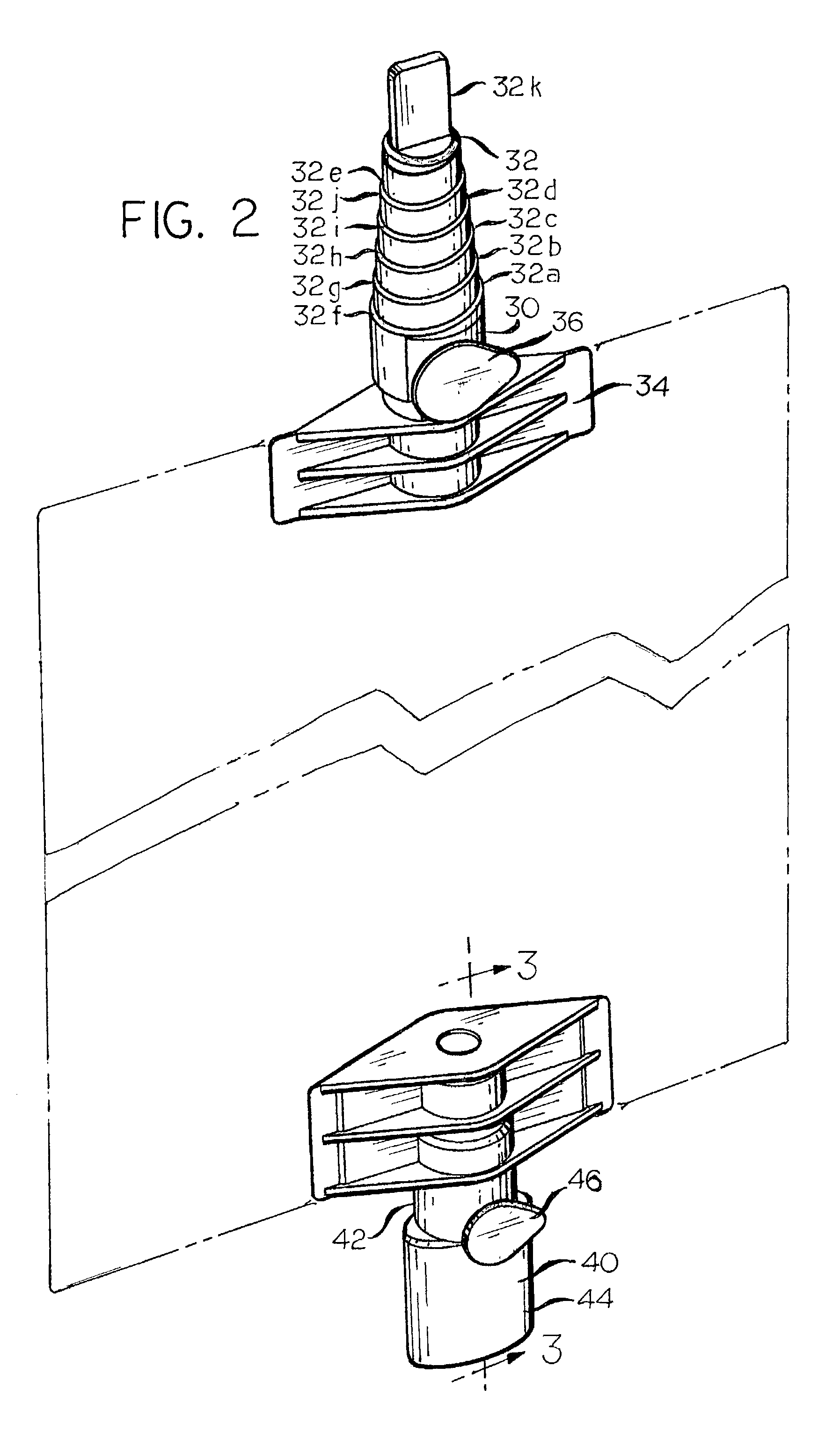
[0009]The urine collection device of the present invention also has a two-piece outlet fitment, an outer, fixed member of which is heat-staked to the urine collection bag at the location of an opening of an otherwise closed outlet or lower end of the bag of the urine collection device. The outlet fitment also has an inner valve member that is movable within and with respect to the fixed outer valve member between open to flow and closed to flow positions, and the movement of the inner valve member is manually by a patient to whom the bag is removably attached, and may be done in a single-hand motion. Fluid moves within the outlet fitment inner valve member, which is annular in cross-section with a closed, innermost free end in a straight through manner, with the seat between an innermost, frusto-conical surface on the inner valve member and a complimentary frusto-conical seat on the outer valve member. Slots in a well of the inner valve member, near its closed end, permit fluid to be withdrawn from the bag of the urine collection device to flow through the interior of the inner valve, the valve also having an annular seal at a location between its closed end and its outer end to prevent fluid from escaping in an annulus between the inner valve member and the outer valve member.
[0011]Accordingly, it is an object of the present invention to provide an improved method of and apparatus for collecting urine from a patient. More particularly, it is the object of the present invention to provide a method and apparatus of the foregoing character that is simpler in construction, while still being functionally in compliance with all known requirements, than known prior art urine collection devices and methods.

Problems solved by technology

However, the varying extents of such steps, which extend normally of a flow axis of the fitment, can often lead to difficulty in manually, securely attaching an inlet tube to the inlet fitment.
However, the device of the '300 patent requires the use of a pair of straps at each location, with a releasable hook and loop (Velcro) connection between free ends of each, and this is an expensive construction.
However, known elastic strap engaging devices involve the use of a separate, molded strap-receiving button at each location, and this involves additional manufacturing and assembly costs that could be avoided if the strap receiving button at each location was molded integrally in a single piece with the fitment with which it is associated.

Method used


Image

  • Urine collection method and apparatus
  • Urine collection method and apparatus
  • Urine collection method and apparatus

Examples


Embodiment Construction

[0017]A urine collection device according to the present invention is generally indicated in FIG. 1 by reference numeral 10. The urine collection device 10 is made up of a flexible, urine collection bag 20, an inlet fitment 30 by which urine can be introduced into the flexible bag 20 and an outlet fitment 40, which functions as a valve and by which urine contained in the bag 20 may be withdrawn therefrom, when desired.

[0018]The urine collection bag 20 is fabricated from a flexible sleeve of a suitable plastic material, for example, polyethylene or polyvinyl chloride. The bag 20 is initially open at its upper and lower ends 22, 24, respectively, and the inlet fitment 30, which is molded in one piece from a thermoplastic material that is capable of being heat-staked to the bag 20, is heat-staked to an opening at the upper end 22 of the bag 20, the upper end 22 otherwise being closed to flow by heat-staking along lines identified by reference numerals 26. Likewise, the outlet fitment 4...


PUM


Abstract

A urine collection device (10) that is made up of a flexible, thermoplastic urine collection bag (20), which receives urine through a molded plastic inlet fitment (30) that is secured to an upper end of the bag 5 and discharges urine through a two-piece molded plastic valve fitment (40) at a lower end of the bag. The inlet fitment, which has no check valve therein, has a series of steps gradually reducing lateral extent as it extends longitudinally from the bag to a free end thereof, and each of the steps extends at a non-perpendicular angle to the longitudinal central axis of the inlet fitment. The bag is also free of any check or flutter valve. The outlet valve fitment has a fixed outer element (42) surrounding an inner element (44) that is rotatable with respect to the outer element to selectively open or close the outlet valve fitment to flow.

Description

FIELD OF THE INVENTION[0001]This invention relates to a method of and an apparatus for collecting urine from a human patient. More particularly, this invention relates to a method and apparatus of the foregoing character that reduces the number of parts required in collecting urine according to known urine collection methods and apparatus.BACKGROUND OF THE INVENTION[0002]U.S. Pat. No. 4,828,554 (Griffin) discloses a urine collection device that includes a collection bag (12) into which urine flows through a line that has a one way flow valve (10) in it, the bag and valve being separate elements. The requirement that the valve and the bag be separate elements involves costs in manufacturing and assembly of the elements that could be reduced if the functions of these elements could be combined into a single element.[0003]Other known prior art urine collection devices, for example, as taught by U.S. Pat. No. 4,421,509 (Schneider et al.), substitute a separate member in the urine collec...

Claims


Application Information

Patent Timeline
IPC IPC(8): A61M1/00
CPCA61F5/4405
Inventor KAMP, DAVID C.
Owner REXAM HEALTHCARE PACKAGING
Learn More