Rotary scanning laser head with coaxial refractive optics

a laser head and coaxial technology, applied in metal-working equipment, welding equipment, manufacturing tools, etc., can solve the problems of unavoidable reflective energy loss at each reflection, small amount and rate of scanning, and unfavorable high-power laser beam scanning, and achieve the effect of reducing the number of reflections

Active Publication Date: 2006-03-07
GEN LASERTRONICS
View PDF7 Cites 47 Cited by
  • Summary
  • Abstract
  • Description
  • Claims
  • Application Information

AI Technical Summary

Benefits of technology

[0074]Safety mechanisms to automatically disable the laser beam under conditions potentially damaging to the apparatus

Problems solved by technology

This type of reflective system results in unavoidable reflective energy loss at each reflection.
The amount and rate of scanning are relatively small and not conducive to high power laser beam scanning, however.
The beam steering mechanism disclosed uses reflective media with the consequent reflective energy loss.

Method used


Image

  • Rotary scanning laser head with coaxial refractive optics
  • Rotary scanning laser head with coaxial refractive optics
  • Rotary scanning laser head with coaxial refractive optics

Examples


Embodiment Construction

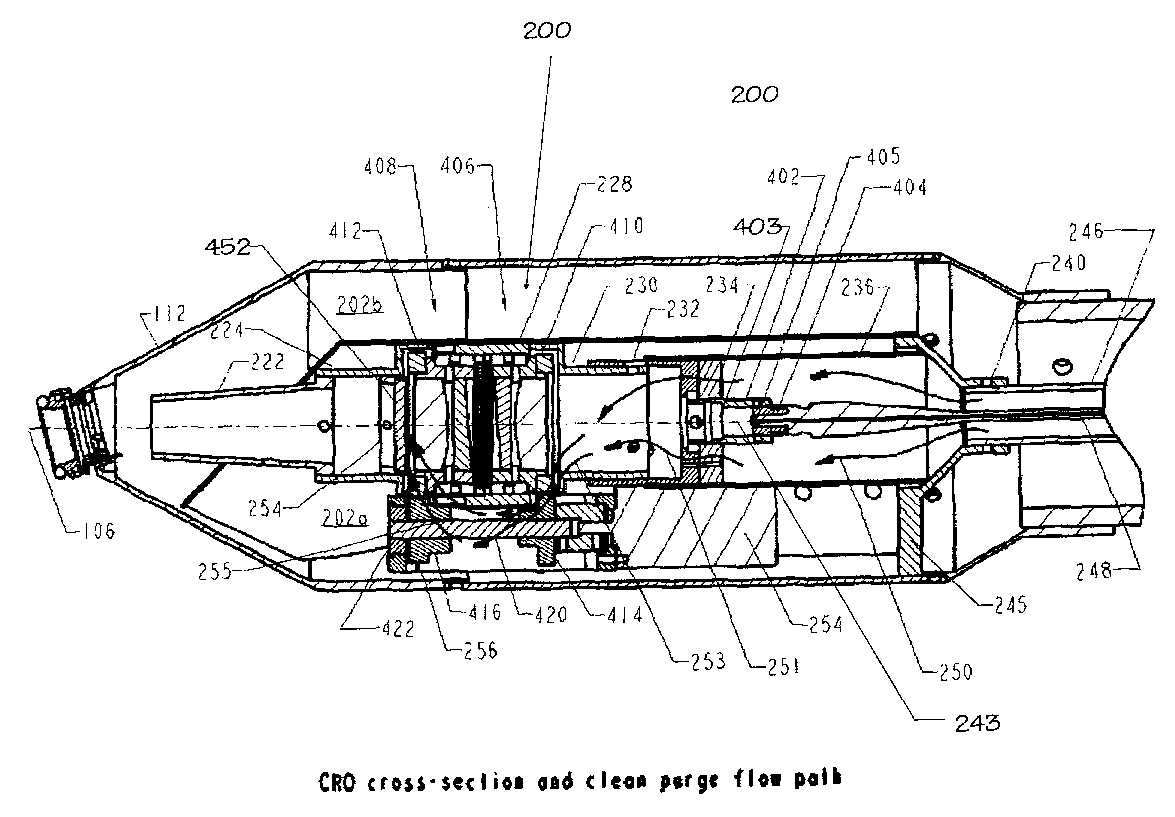
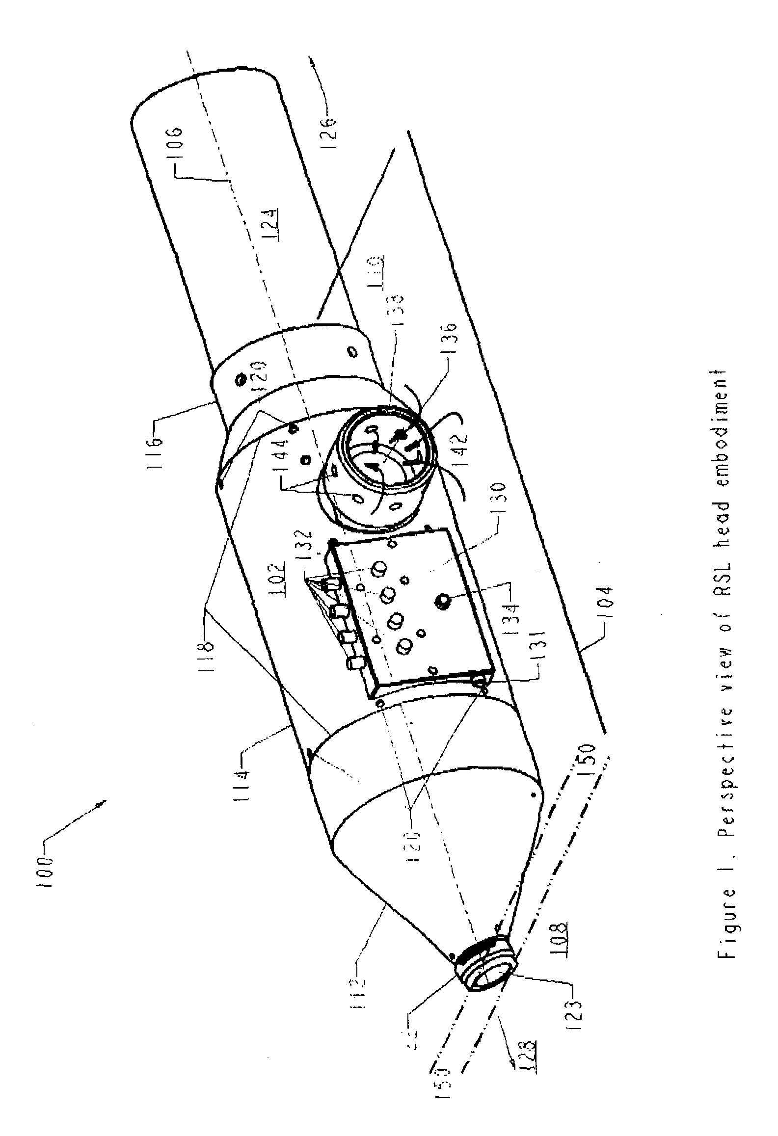
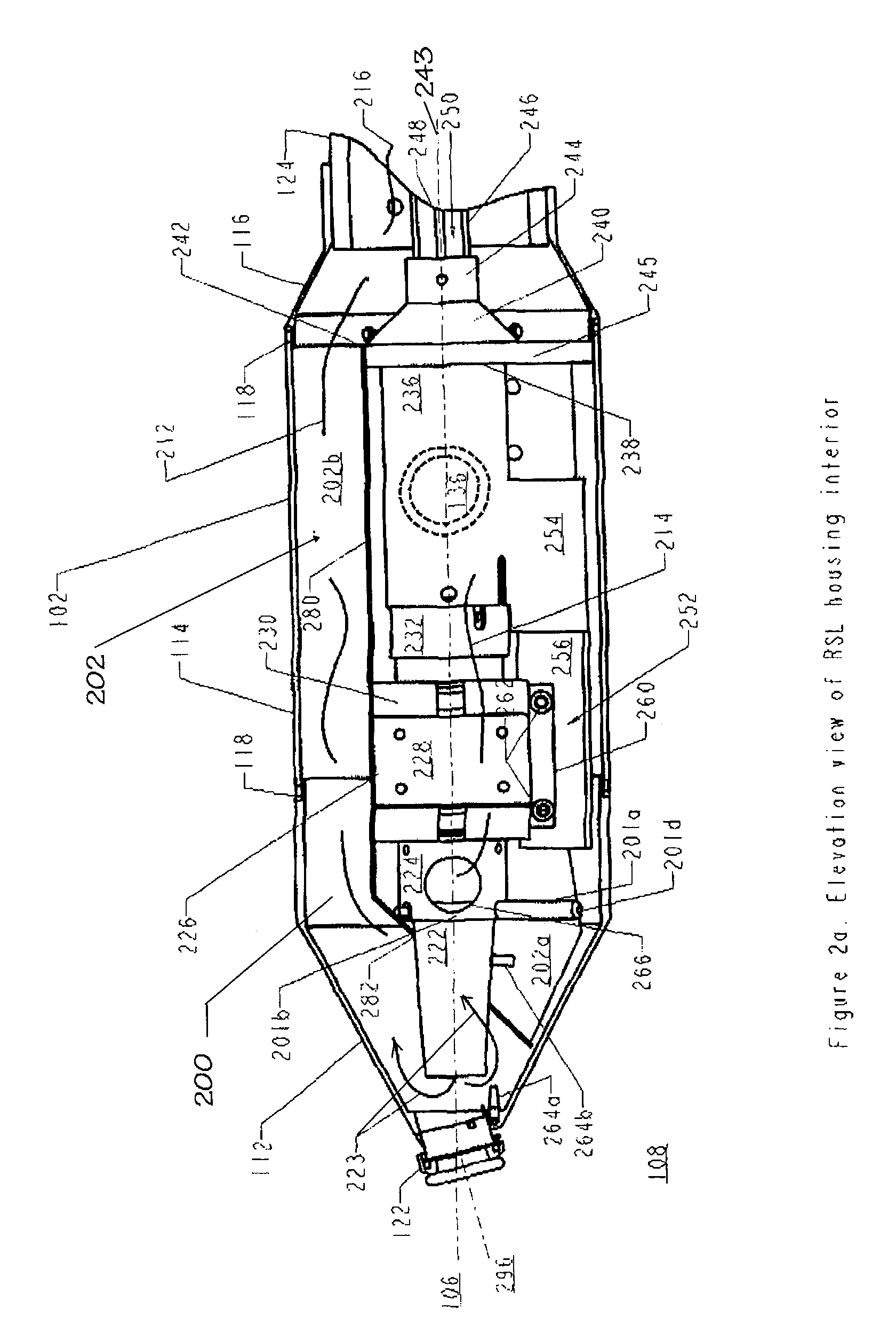
[0089]With reference to FIG. 1 there is shown an external perspective view of one preferred embodiment 100 of the present Rotary Scanning Laser (RSL) head invention incorporating an embodiment of the present CRO invention. The RSL head 100 has a longitudinal housing 102 with a longitudinal body of length 104 aligned along a central axis 106 between a proximal nose end 108 and a spaced apart distal hose coupling end 110. The housing 102 forms a closed, continuous rigid shell with an essentially circular cross-section, tapered at the two ends. The housing is assembled from three rigid, thin wall body sections 112, 114, 116 joined at overlapping adjacent ends 118.

[0090]The RSL head 100 is a compact, hand held laser-scanning head capable of receiving, delivering and directing radiant energy in a precisely controlled pattern. The head 100 is coupled to a high intensity external radiant energy source (e.g., a high power, fiber guided input laser beam) received through a flexible service h...


PUM

PropertyMeasurementUnit
angleaaaaaaaaaa
velocityaaaaaaaaaa
velocityaaaaaaaaaa

Abstract

A rotary refractive laser scanner head uses two sets of lenses and prisms aligned along a common optical axis. Each prism is paired with one of the lenses. The lens-prism pairs are separately mounted rotatable on a common axis coaxial with the optical axis. A motor drives two gear sets. Each gear set is separately coupled to one of the two lens-prism pairs and rotates them at selected, typically different speeds. An input laser beam is directed along the optical axis at one of the lens-prism pairs. The first pair collimates and refracts the input beam into an intermediate deflected beam according to Snell's law and the characteristics of the laser beam and optics. The second pair receives the intermediate beam and further deflects it to form an output beam. By selecting the motor speed, gear ratios, optics spacing, characteristics and prism wedge (deflection) angle, the scanner head effectively can scan an output laser beam over a desired pattern area.

Description

[0001]This application claims priority benefit of Provisional Application No. 60 / 329,388 filed Oct. 13, 2001.[0002]The U.S. Government has a paid-up license in this invention as provided for by the terms of DCMA Contract FO9650-99-C-0195, dated 6 May 1999, subject to FAR 52.227-11 (c), “Patent Rights—Retention by the Contractor”BACKGROUND OF THE INVENTION[0003]Delivery of certain wavelengths of radiant energy is facilitated by transmission along flexible silica fibers. The energy is dispersed from the emitting end of an optical fiber in a widening cone. The energy intensity is generally symmetric about the central fiber axis (i.e., uniformly distributed in azimuth) at the emitting end. The distribution of emitted energy orthogonal to the azimuth angle is highly non-uniform, with highest intensity at the central axis, rapidly decreasing with increasing divergence angle relative to the central fiber axis, sometimes approximated by a power cosine function of the divergence angle.[0004]...

Claims


Application Information

Patent Timeline
Patent Type & Authority Patents(United States)
IPC IPC(8): B23K26/36
CPCB23K26/0807B23K26/0096B23K26/082
Inventor WOOL, MITCHELL R.THOMAS, JAMES W.
Owner GEN LASERTRONICS
Why Eureka
Try Eureka