
Laminated glass plane with electrically controlled functional element

a functional element and laminated glass technology, applied in the direction of lighting and heating equipment, transportation and packaging, coatings, etc., can solve the problems of reducing the lifetime and affecting the color intensity of the el lighting element in operation, so as to improve the color constancy of the el lighting element, improve the thermal comfort of the vehicle, and improve the effect of functional element properties

Inactive Publication Date: 2006-03-07
SAINT-GOBAIN GLASS FRANCE
View PDF5 Cites 15 Cited by
  • Summary
  • Abstract
  • Description
  • Claims
  • Application Information

AI Technical Summary

Benefits of technology

[0016]The electrode layers, the electroluminescent layer itself and the dielectric layer may be deposited by thick film screen printing on suitable substrates, such as glass or PET sheets. This known effect produces surface lighting effects which can be used for many purposes (lighting, logos, luminous signs), if the relatively low light density and the choice of colors, limited by the materials that can be used, are acceptable. Furthermore, the electroluminescent elements themselves (hereafter called lighting elements) are not transparent so that a surface provided with them cannot let light through (in daylight).
[0019]The object of the invention is to reduce the temperature-induced variations in the properties of an electrically controllable functional element placed on or in a laminated panel assembly.
[0022]Thus, the functional element is coupled to a surplus heating film which makes it possible, in all cases at low ambient temperatures, to increase the temperature of the functional element up to the range in which its optical properties, for example the tint of the light emitted, were designed.
[0028]In addition to the positive effect on the properties of the functional element, in particular the better color constancy of an EL lighting element, this heating film furthermore allows the thermal comfort in a vehicle to be improved, specifically when the laminated panel assembly is placed in the roof region.

Problems solved by technology

When such EL lighting elements, made of a thick inorganic film of large area, operate, especially in motor vehicles, it turns out that differences in the color emitted may, however, result when there are variations in temperature.
Admittedly, these lighting elements in operation gives off a certain amount of heat because of the power that they dissipate; however, in practice this is negligible.
Trials carried out for the purpose of balancing the luminous tint by injection of the frequency of the supply voltage result in a drastic reduction in the lifetime of the EL lighting element.
Furthermore, the electroluminescent elements themselves (hereafter called lighting elements) are not transparent so that a surface provided with them cannot let light through (in daylight).
These elements may also introduce undesirable variations in the instantaneous degree of transmission at extreme temperatures.
In this case, a separate opaque coating is unnecessary because the electroluminescent layers themselves do not let visible light through.

Method used


Image

  • Laminated glass plane with electrically controlled functional element
  • Laminated glass plane with electrically controlled functional element
  • Laminated glass plane with electrically controlled functional element

Examples


Embodiment Construction

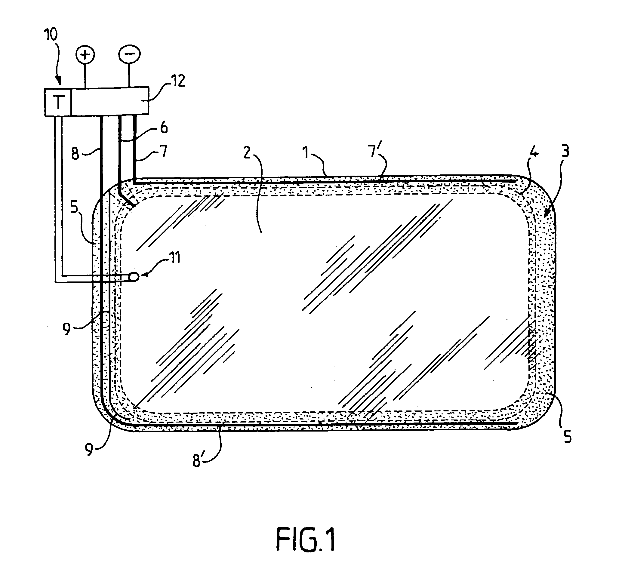
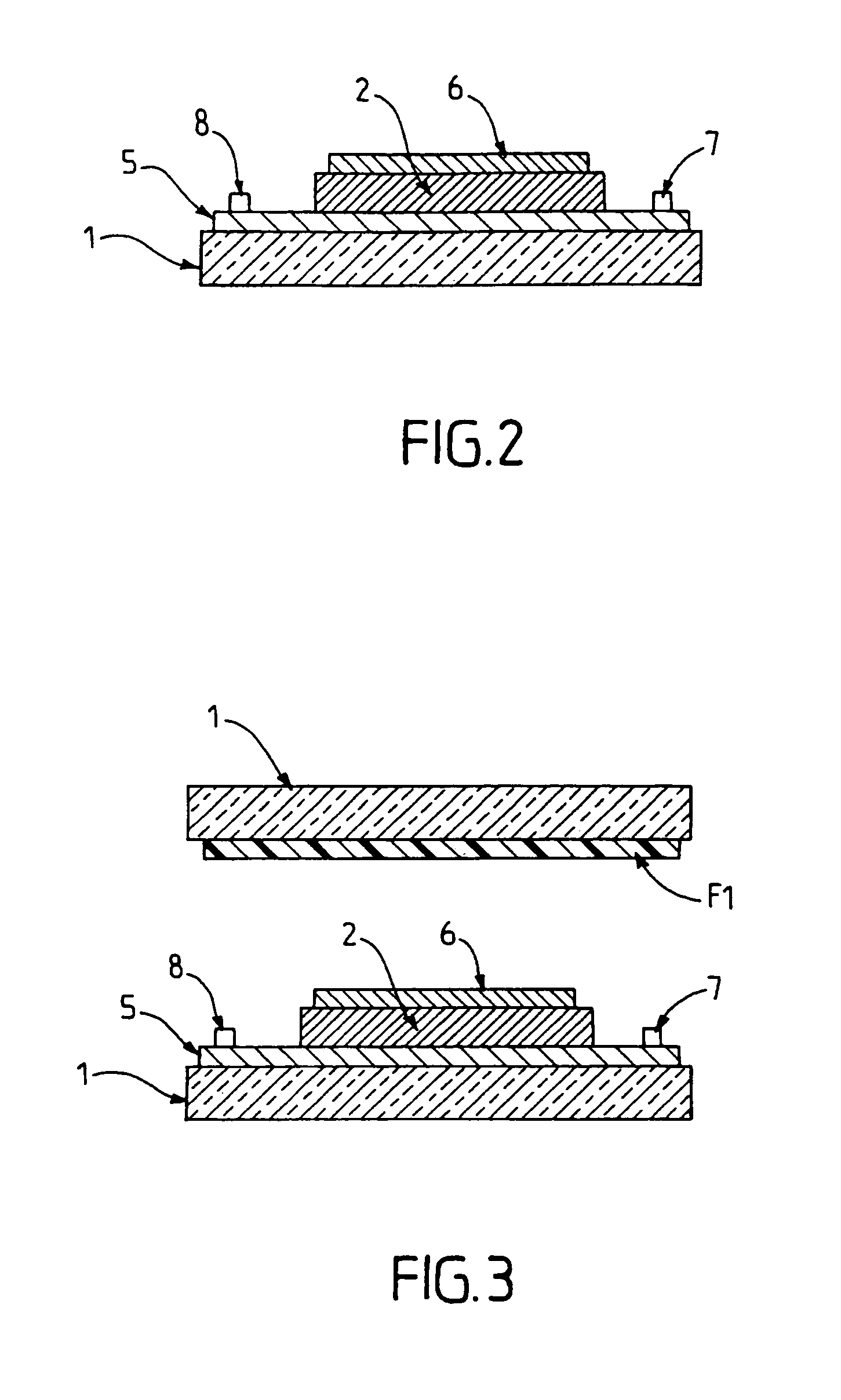
[0036]Further details and advantages of the subject matter of the invention will become apparent from the drawings of illustrative examples and from the detailed description which follows. The description is given with reference to an EL lighting element, without however wishing to thus exclude other functional elements for this application.

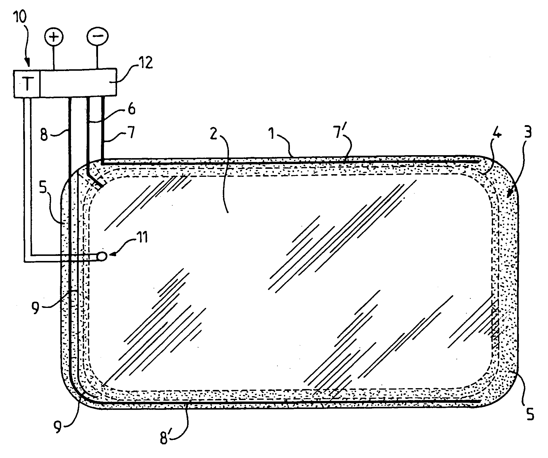
[0037]FIG. 1 shows, in a simplified representation and as an example, a view of a panel assembly with an EL lighting element and an electrical heating coating.

[0038]A rigid panel 1 supports an EL lighting element 2, which extends over practically the entire area of the surface of the panel 1, but which leaves a peripheral edge region 3 of the panel free. A dotted line 4 denotes the boundary of an external edge strip on the face of the panel, which may be covered by an opaque colored film which serves as visual protection. Of course, this boundary may also lie within that area of the surface of the panel 1 which is covered by the EL lighting eleme...


PUM

PropertyMeasurementUnit
Temperatureaaaaaaaaaa
Electric potential / voltageaaaaaaaaaa
Optical propertiesaaaaaaaaaa

Abstract

The invention concerns a laminated glass pane (1) with at least a rigid pane and a flat electrically controlled functional element (2) as well as at least a thin electrically conductive coat (5), wherein, in accordance with the invention, the coat (5) also constitutes a flat electrode of the functional element, the coat being capable of being heated by being powered with an electric voltage, independently of the power supply of the functional element (2). Thus, unwanted variations of the optical properties of the functional elements are reduced when such a laminated glass pane is used at highly fluctuating temperatures, in particular at low temperatures.

Description

CROSS-REFERENCE TO RELATED APPLICATIONS[0001]The present application is the U.S. counterpart of WO 03 / 056880, and claims priority to German application number 01 / 10164063.3 filed on Dec. 24, 2001, the entire contents of each of which are incorporated herein by reference.BACKGROUND OF THE INVENTION[0002]1. Field of the Invention[0003]The invention relates to a laminated panel assembly comprising at least one rigid panel, an electrically controllable flat functional element, such as an electroluminescent lighting element, and at least one electrically conducting thin film.[0004]2. Description of the Background Art[0005]The term “laminated panel assembly” is understood here to mean a unit consisting of a rigid panel and of the functional element, which is itself composed of several films and joined to the rigid panel, or alternatively applied thereto. The term “functional elements” is understood to mean, within the context of the present description, flat elements such as electrolumine...

Claims


Application Information

Patent Timeline
IPC IPC(8): H05B3/00H05B44/00F21W106/00H05B3/84H05B3/86H05B33/14H05B33/26
CPCB32B17/10036B32B17/10174B32B17/10495H05B3/86H05B3/84H05B33/14H05B33/26H05B33/10H05B44/00H10K50/11H10K50/805
Inventor MAEUSER, HELMUT
Owner SAINT-GOBAIN GLASS FRANCE
Learn More