
Apparatus and methods for modulating refractive index

a refractive index and apparatus technology, applied in non-linear optics, instruments, optics, etc., can solve the problems of limiting high manufacturing costs of devices, and affecting the applicability of devices,

Active Publication Date: 2006-03-07
ECLIPSE ENERGY SYST
View PDF75 Cites 25 Cited by
  • Summary
  • Abstract
  • Description
  • Claims
  • Application Information

AI Technical Summary

Benefits of technology

[0011]In accordance with this invention, a thin film structure that is capable of ion intercalation or release, where the ion intercalation or release is accompanied by a change of refractive index without significant optical absorption at the wavelength of interest or at the operating wavelength is provided. The thin film structure is referred to herein as an “iono-refractive structure” because it includes one or more ion insertion layers having a real portion and an imaginary portion of the dielectric constant. While both the real portion and the imaginary portion of the dielectric constant change, the change in the imaginary portion is either less than the change in the real portion or limited to acceptable values specific to the operation of a particular device at the wavelength of interest or at the operational wavelength. The iono-refractive structure may be suitable for the fabrication of or integration with tunable optical filters, wavelength-selective optical elements, active modulated interferometers, variable phase shifters, sensors, lenses, and other optical components.

Problems solved by technology

Moreover, while each of these approaches provides some change in refractive index, these approaches generally suffer from high manufacturing costs, constraints on the operating environment (e.g., temperature and pressure), and drawbacks related to system and substrate compatibility.
Even further, many of these approaches significantly change the transmissivity while changing the refractive index, thereby limiting the applicability of the device.

Method used


Image

  • Apparatus and methods for modulating refractive index
  • Apparatus and methods for modulating refractive index
  • Apparatus and methods for modulating refractive index

Examples


Embodiment Construction

[0020]The present invention involves thin film structures. For convenience herein, these thin film structures are sometimes referred to as “iono-refractive structures” or “iono-refractive circuits” because they include one or more ion insertion layers having a real portion and an imaginary portion of the dielectric constant. While both the real portion of the dielectric constant and the imaginary portion of the dielectric constant change, the change in the imaginary portion is either less than the change in the real portion or limited to acceptable values specific to the operation of a particular device at the wavelength of interest or at the operational wavelength.

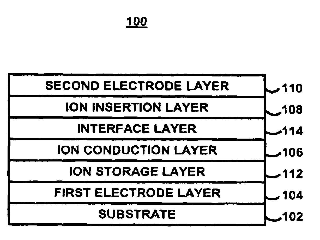
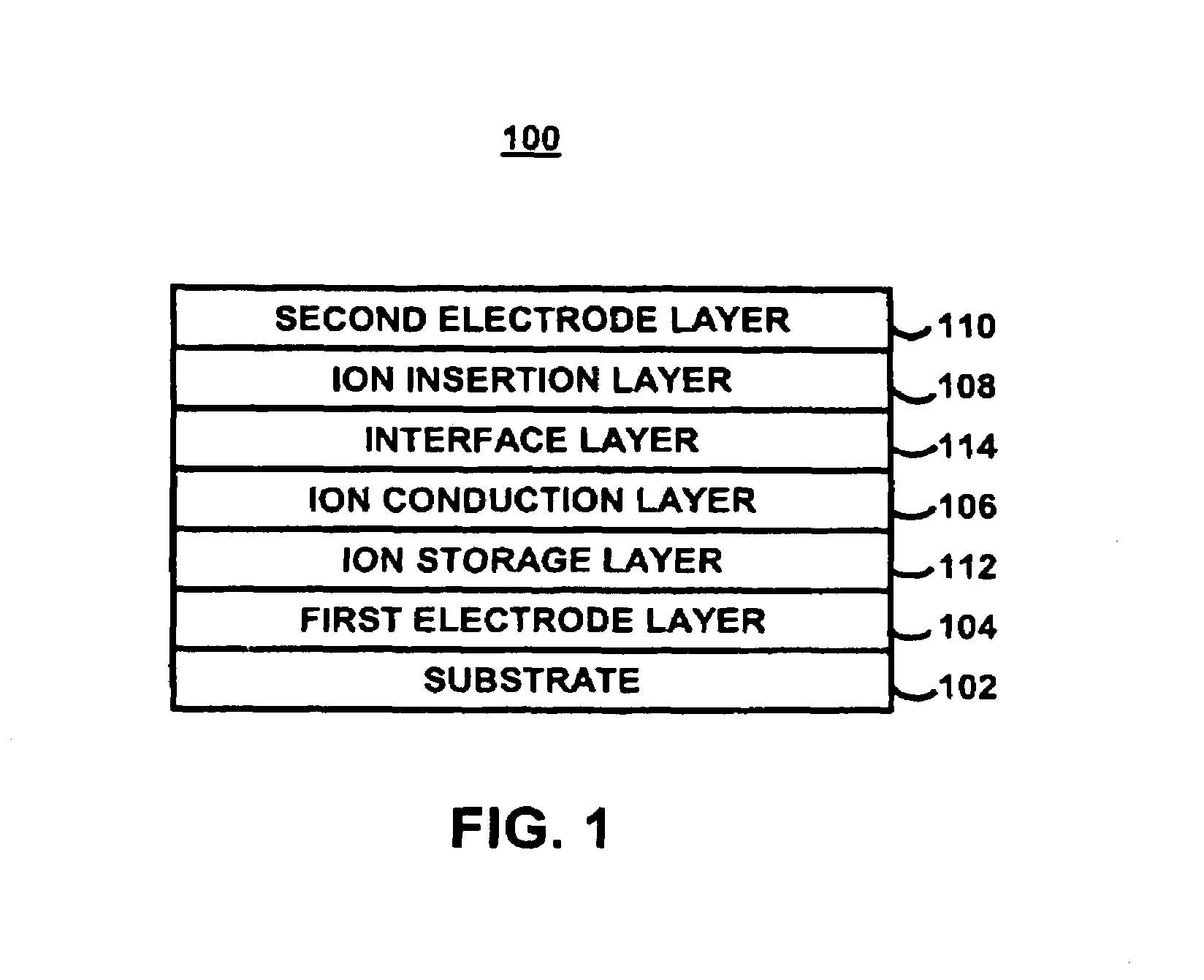
[0021]FIG. 1 illustrates schematically, in cross section, a portion of an iono-refractive structure 100 which may be relevant to or useful in connection with certain embodiments of the present invention. Structure 100 includes a substrate 102, a first electrode layer 104, an ion conduction layer 106, an ion insertion laye...


PUM

PropertyMeasurementUnit
wavelengthaaaaaaaaaa
refractive indexaaaaaaaaaa

Abstract

An iono-refractive structure that includes one or more ion insertion layers having a real portion and an imaginary portion of the dielectric constant is provided. While both the real portion and the imaginary portion of the dielectric constant change, the change in the imaginary portion is less than the change in the real portion at the wavelength of interest or at the operational wavelength. The iono-refractive structure may be suitable for the fabrication of or integration with tunable optical filters, wavelength-selective optical elements, active modulated interferometers, optical phase shifters, optical phased array beam steering, optical phased array beam tracking, tunable optical filters, sensors, variable lenses, tunable diffraction gratings, and other optical components.

Description

CROSS-REFERENCE TO RELATED APPLICATIONS[0001]This application claims the benefit of U.S. provisional application No. 60 / 421,617, filed Oct. 25, 2002, which is hereby incorporated by reference herein in its entirety.BACKGROUND OF THE INVENTION[0002]The present invention relates to apparatus and methods for modulating refractive index. More particularly, the invention relates to inducing a change of refractive index in one or more layers of an iono-refractive structure that are capable of ion intercalation or release. The ion intercalation or release is accompanied by a change of refractive index without a significant increase in the optical absorption at the wavelength of interest or at the operating wavelength. The structure may be suitable for the fabrication of or integration with tunable optical filters, wavelength-selective optical elements, active modulated interferometers, variable phase shifters, sensors, lenses, and other optical components.[0003]Various approaches have been...

Claims


Application Information

Patent Timeline
Patent Type & Authority Patents(United States)
IPC IPC(8): G02F1/01G02F1/19
CPCG02F1/1523G02F1/19G02F2001/213G02F1/3137G02F1/3136G02F1/213
Inventor WESTFALL, RAYMOND T.GROGER, HOWARD P.
Owner ECLIPSE ENERGY SYST
Learn More