
Integrity check in a communication system

a communication system and integrity check technology, applied in the field of integrity check in communication systems, can solve the problems of system vulnerability to man-in-the-middle attacks, system may be vulnerable to “replay attacks”, and the room for unauthorized manipulation, insertion and deletion of subsequent messages, so as to enhance user security in communication systems and prevent replay attacks.

Inactive Publication Date: 2006-03-07
NOKIA TECHNOLOGLES OY
View PDF9 Cites 76 Cited by
  • Summary
  • Abstract
  • Description
  • Claims
  • Application Information

AI Technical Summary

Benefits of technology

The present invention provides a method for secure communication between two nodes using multiple channels. The method involves calculating an integrity output based on a set of values, one of which is the identity of the channel, and transmitting this information between the nodes. This method prevents replay attacks and ensures that different channels within a connection will never use the same set of input parameters for calculating the message authentication code. The invention enhances user security in communication systems and ensures that parallel communication channels within a connection will never use same set of input parameters for calculating the message authentication code.

Problems solved by technology

Telecommunications are subject to the problem of ensuring that the received information is sent by an authorised sender and not by an unauthorised party who is trying to masquerade as the sender.
The problem is especially relevant to cellular telecommunication systems, where the air interface presents an potential opportunity for an unauthorised party to eavesdrop and replace the contents of a transmission.
However, this procedure leaves room for the unauthorized manipulation, insertion, and deletion of subsequent messages.
If there are several communication channels in use which all use the same secret key the following problem arises.
However the method, which has been proposed, permits the identical message to be sent on two different signalling radio bearers at different times. This makes the system vulnerable to man-in-the-middle attacks.
In particular, such a system may be vulnerable to the “replay attack” described above.

Method used


Image

  • Integrity check in a communication system
  • Integrity check in a communication system
  • Integrity check in a communication system

Examples


Embodiment Construction

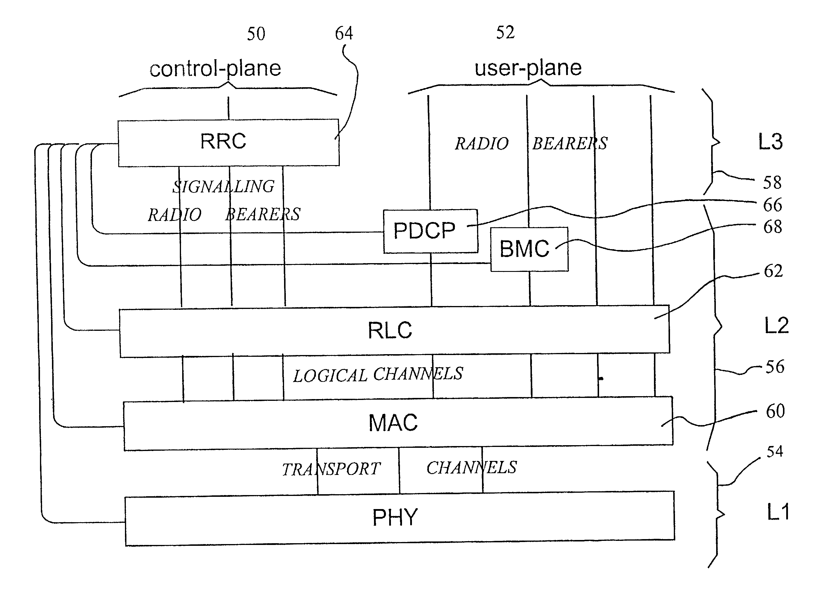
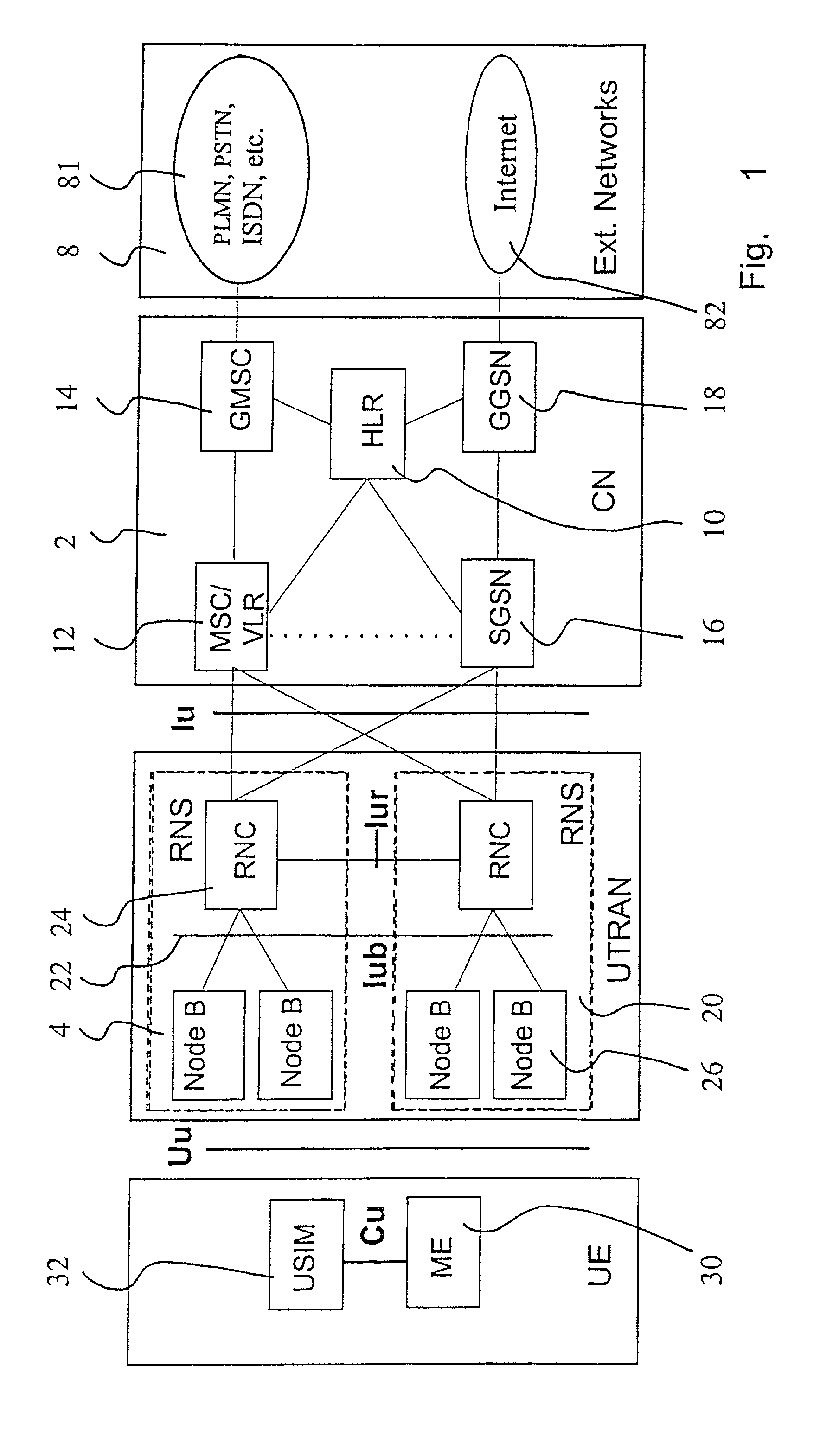
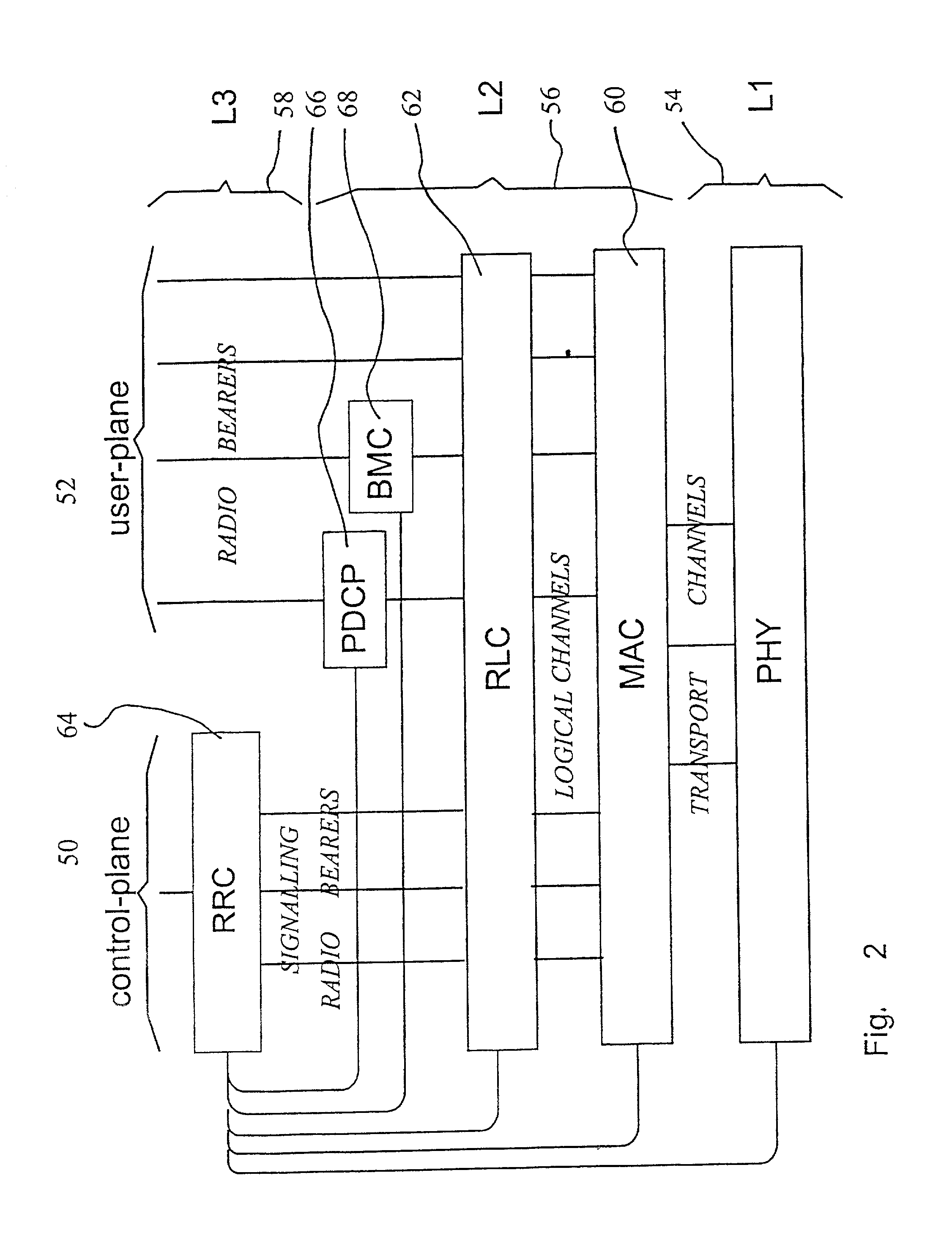
[0040]With reference to FIG. 1, a typical mobile telephone system structure will be described. The main parts of the mobile telephone system are: a core network CN 2, a UMTS terrestrial radio access network UTRAN 4, and user equipment UE 6. The core network CN 2 can be connected to external networks 8, which can be either Circuit Switched (CS) networks 81 (e.g. PLMN, PSTN, ISDN) or Packet Switched (PS) networks 82 (e.g. the internet). The interface between the core network CN 2 and the UMTS terrestrial radio access network UTRAN 4 is called the lu interface, and the interface between the UMTS terrestrial radio access network UTRAN 4 and the user equipment UE 6 is called the Uu interface. As shown in FIG. 1, the RNC is connected to two CN nodes (MSC / VLR and SGSN). In some network topologies it may be possible that one RNC is connected to one CN node or to more than two CN nodes.

[0041]The core network CN 2 is composed of a Home Location Register HLR 10, a Mobile Services Switching Cen...


PUM


Abstract

A method of communication between a first node and a second node for a system where a plurality of different channels is provided between said first and second node. The method comprises the step of calculating an integrity output. The integrity output is calculated from a plurality of values, some of said values being the same for said different channels. At least one of said values is arranged to comprise information relating to the identity of said channel, each channel having a different identity. After the integrity output has been calculated, Information relating to the integrity output is transmitted from one of said nodes to the other.

Description

[0001]This application is a continuation of PCT / EP01 / 00735 filed Jan. 23, 2001.FIELD OF THE INVENTION[0002]The present invention relates to a method for checking the integrity of communications between a first node and a second node. In particular, but not exclusively, the invention relates to a method for checking the integrity of communications between a mobile station and a cellular network.BACKGROUND TO THE INVENTION[0003]Various different telecommunication networks are known. A telecommunication network is a cellular telecommunication network, wherein the area covered by the network is divided into a plurality of cells. Each cell is provided with a base station, which serves mobile stations in the cell associated with the base station. User equipment, such as mobile stations, thus receive signals from and transmit signals to the base station, and thereby may communicate through the base stations. The cellular system also typically comprises a base station controller controlling...

Claims


Application Information

Patent Timeline
Patent Type & Authority Patents(United States)
IPC IPC(8): H04J1/16H04M3/42H04L9/16H04L9/18H04W12/00
CPCH04L63/08H04L63/0869H04W76/021H04W12/06H04L63/123H04W12/10H04W12/02H04W76/11H04W12/037
Inventor VIALEN, JUKKANIEMI, VALTTERI
Owner NOKIA TECHNOLOGLES OY
Learn More