Signal waveform detection circuit

a signal waveform and detection circuit technology, applied in the direction of amplitude demodulation, transmission monitoring, instruments, etc., can solve the problem of inability to detect signals in real time, and achieve the effect of avoiding large circuit scal

Inactive Publication Date: 2006-03-07
LAPIS SEMICON CO LTD
View PDF10 Cites 11 Cited by
  • Summary
  • Abstract
  • Description
  • Claims
  • Application Information

AI Technical Summary

Problems solved by technology

However, in the case of the conventional circuit, after the electric potential of the common emitter of the differential pair in each differential amplifying circuit constructing the amplifying circuit is converted to an electric current, no RSSI signal of the digital signal can be detected unless processing for calculating a sum total of the electric currents by the adding circuit and then further converting the sum total of the electric currents to a voltage and comparing this voltage with the threshold value is performed.
Therefore, a problem exists in that the circuit scale is inevitably large-sized.

Method used


Image

  • Signal waveform detection circuit
  • Signal waveform detection circuit
  • Signal waveform detection circuit

Examples


first embodiment

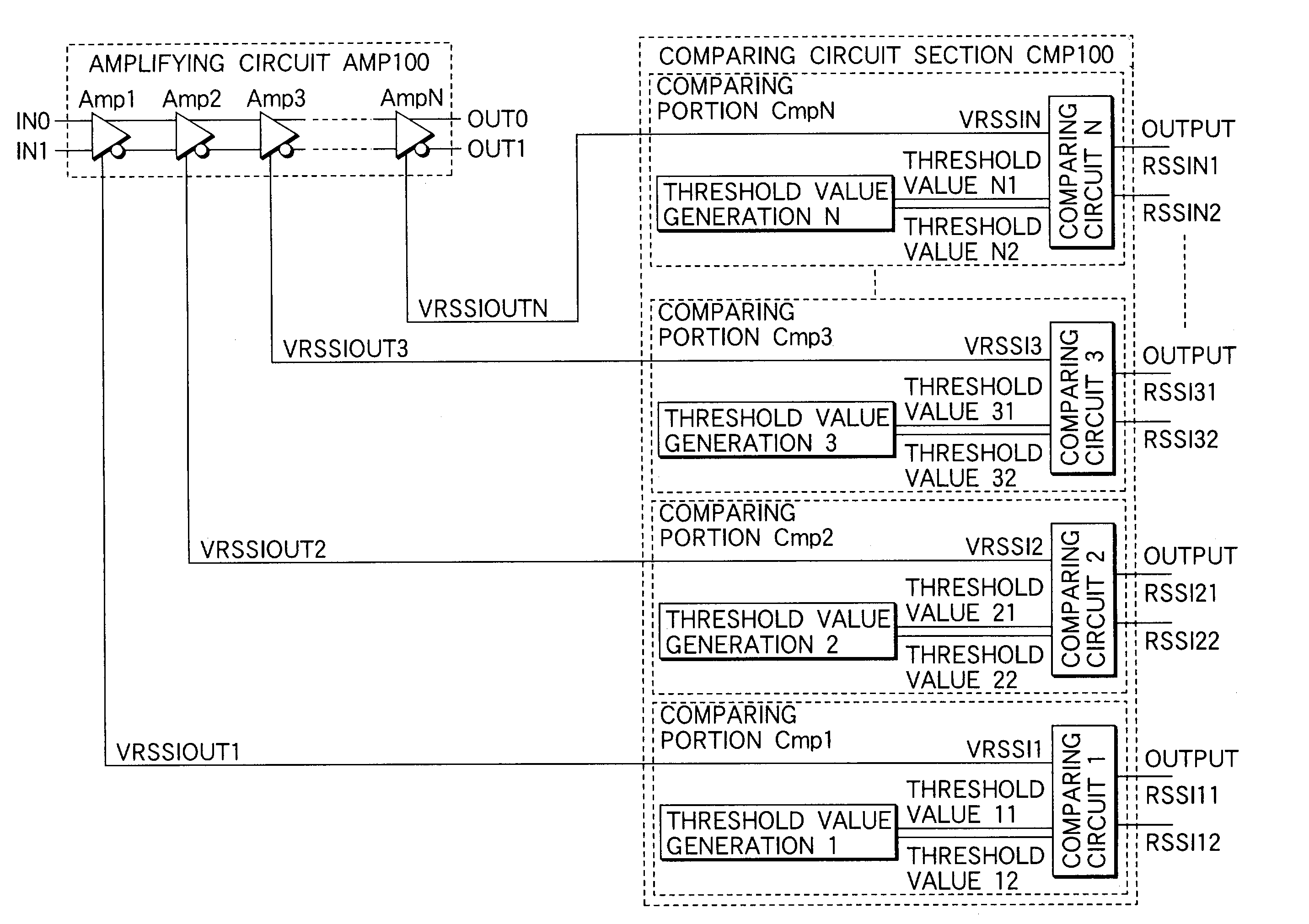
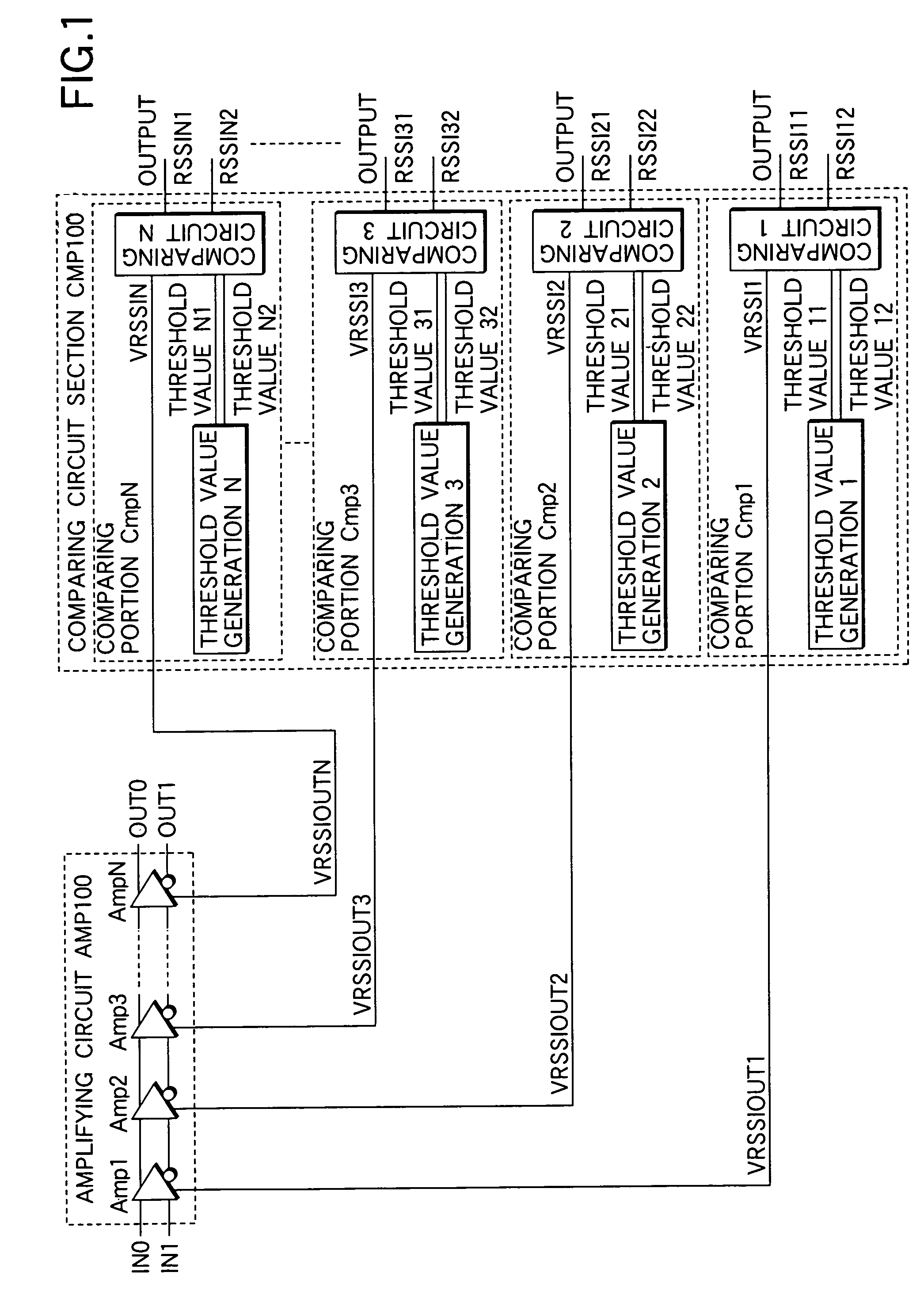
[0034]FIG. 1 shows the function block construction of a signal amplitude detection circuit in accordance with a As shown in FIG. 1, the signal amplitude detection circuit has an amplifying circuit AMP100 constructed by N-differential amplifying circuits Amp1 to AmpN, and a comparing circuit section CMP100.

[0035]The detailed construction of the amplifying circuit AMP100 will be described later. The comparing circuit section CMP100 has a construction for individually executing the comparison of voltages VRSSIOUT1 to VRSSIOUTN appearing in a common node of each differential amplifying circuit constituting the amplifying circuit AMP100, and the respective corresponding threshold values.

[0036]The comparing circuit section CMP100 has N-comparing portions Cmp1 to CmpN corresponding to the respective differential amplifying circuits constructing the amplifying circuit AMP100. One threshold value generating portion and one comparing circuit are arranged in each comparing portion.

[0037]The t...

second embodiment

[0079]The parallel / serial conversion and header / footer adding circuit PS200 is also the same as the second embodiment in that this parallel / serial conversion and header / footer adding circuit PS200 has two function portions constructed by a parallel / serial converting function portion and a header / footer signal adding function portion.

[0080]The parallel / serial conversion and header / footer adding circuit PS200 differs from that in the second embodiment in that the number of input lines of a parallel signal is set to 2×(N-1)+2×N and is therefore large, and the inputted parallel signal is a detecting result with respect to two different circuits.

[0081]The header and the footer may be given two sets of headers and footers in total are added) by the header / footer signal adding function portion separately with respect to the detecting result of a signal amplitude obtained from the filter circuit with the amplifying function and the detecting result of a signal amplitude obtained from the am...

third embodiment

[0087]As mentioned above, in accordance with this third embodiment, it is possible to realize the signal waveform detection circuit for reducing an element number and the circuit scale even when plural (here two) amplifying circuit groups as a detecting object exist.

[0088]Further, the circuit arrangement (including design and layout) can be set to have the degree of freedom.

[0089]In the above first to third embodiments, the number of threshold values given to each comparing circuit is described as two. However, any number of threshold values may be also set if the threshold values are set at an equal interval in the decibel [dB] unit (i.e., logarithmically) between the output VRSSI level when the input signal amplitude of the corresponding amplifying circuit is a maximum amplitude, and the output VRSSI level when the input signal amplitude is a minimum amplitude.

[0090]In the above embodiments, it is described that the threshold value is set in a state in which the minimum electric p...


PUM


Abstract

A signal waveform detection circuit includes an amplifier circuit and a comparing circuit. The amplifier circuit has differential amplifiers connected in series. Each of the differential amplifiers has a common connection point. The comparing circuit is connected to the common connection points of the amplifier circuit. The comparing circuit includes comparing units connected to one of the differential amplifiers. Each of the comparing units has a threshold voltage generating circuit for generating signals. Each signal has a threshold voltage that is set between a maximum threshold voltage of a signal output from the corresponding differential amplifier during a maximum amplitude output and a minimum threshold voltage of a signal output from the corresponding differential amplifier during a minimum amplitude output. The comparing unit further has a comparator comparing a voltage at the common connection point with the threshold voltage.

Description

CROSS REFERENCE TO RELATED APPLICATION[0001]The present application claims priority under 35 U.S.C. 119(e)(1) to U.S. provisional application Ser. No. 60 / 348,377 filed on Jan. 16, 2002.BACKGROUND OF THE INVENTION[0002]The present invention relates to a signal waveform detection circuit utilized in a wireless machine and other receivers, and able to be applied to e.g., a receiver signal strength indicator (RSSI) detection circuit.[0003]There are a wireless machine and other receivers having a detection circuit for detecting a receiver signal strength indicator (an indicator for judging the signal strength of an input signal) signal.[0004]The conventional circuit construction of the receiver having the detection circuit of Japanese Patent Publication No. 25733 / 1992 is illustrated in FIG. 2 of the present application.[0005]The detection circuit is constructed by an amplifying circuit AMP200 and an amplitude detection circuit 201. The amplifying circuit AMP200 is constructed by connecti...

Claims


Application Information

Patent Timeline
Patent Type & Authority Patents(United States)
IPC IPC(8): H04B17/00G06F19/00G06G7/24H03G7/00
CPCH03G7/001
Inventor MATSUMOTO, SHUICHIYOSHIDA, AKIRA
Owner LAPIS SEMICON CO LTD
Why Eureka
Try Eureka