Method for designing a circuit for programmable microcontrollers

a microcontroller and circuit technology, applied in the field of programmable single-chip systems, can solve the problems of not being able to offer designers many tools to reduce the amount of low level details, and conventional software for programming microcontrollers is not very robust,

Inactive Publication Date: 2006-03-07
CYPRESS SEMICON CORP
View PDF22 Cites 76 Cited by
  • Summary
  • Abstract
  • Description
  • Claims
  • Application Information

AI Technical Summary

Benefits of technology

[0014]Another embodiment allows the user to select a new position (e.g., new programmable system block or blocks) for a selected user module. In response to such a user request, a new potential position is computed and displayed for the user module.

Problems solved by technology

However, programming the microcontroller to perform the desired functions can be an arduous task.
Conventional software for programming microcontrollers is not very robust and does not offer designers many tools to reduce the amount of low level details they need to memorize in order to configure the chip.
Conventional software for programming microcontrollers is very difficult to use.
Consequently, the many displayed windows cause confusion because the user needs to keep track of which window is used for which function.
Furthermore, it is very difficult to navigate between the windows because some windows overlap others.
The user may have difficulty remembering which windows contain what information and which windows receive what information.
Unfortunately, this process is tedious and error-prone.
Conventionally, this can be an arduous and error-prone process.
Multifunction input / output (I / O) ports or pins may be very difficult to configure.
Thus, the designer time is not used efficiently and the possibility of errors in the datasheet is great.
Manual programming is very error prone and tedious and difficult to error check.

Method used


Image

  • Method for designing a circuit for programmable microcontrollers
  • Method for designing a circuit for programmable microcontrollers
  • Method for designing a circuit for programmable microcontrollers

Examples


Embodiment Construction

[0024]In the following detailed description of the present invention, a method for facilitating programming a microcontroller, numerous specific details are set forth in order to provide a thorough understanding of the present invention. However, it will be recognized by one skilled in the art that the present invention may be practiced without these specific details or with equivalents thereof. In other instances, well known methods, procedures, components, and circuits have not been described in detail as not to unnecessarily obscure aspects of the present invention.

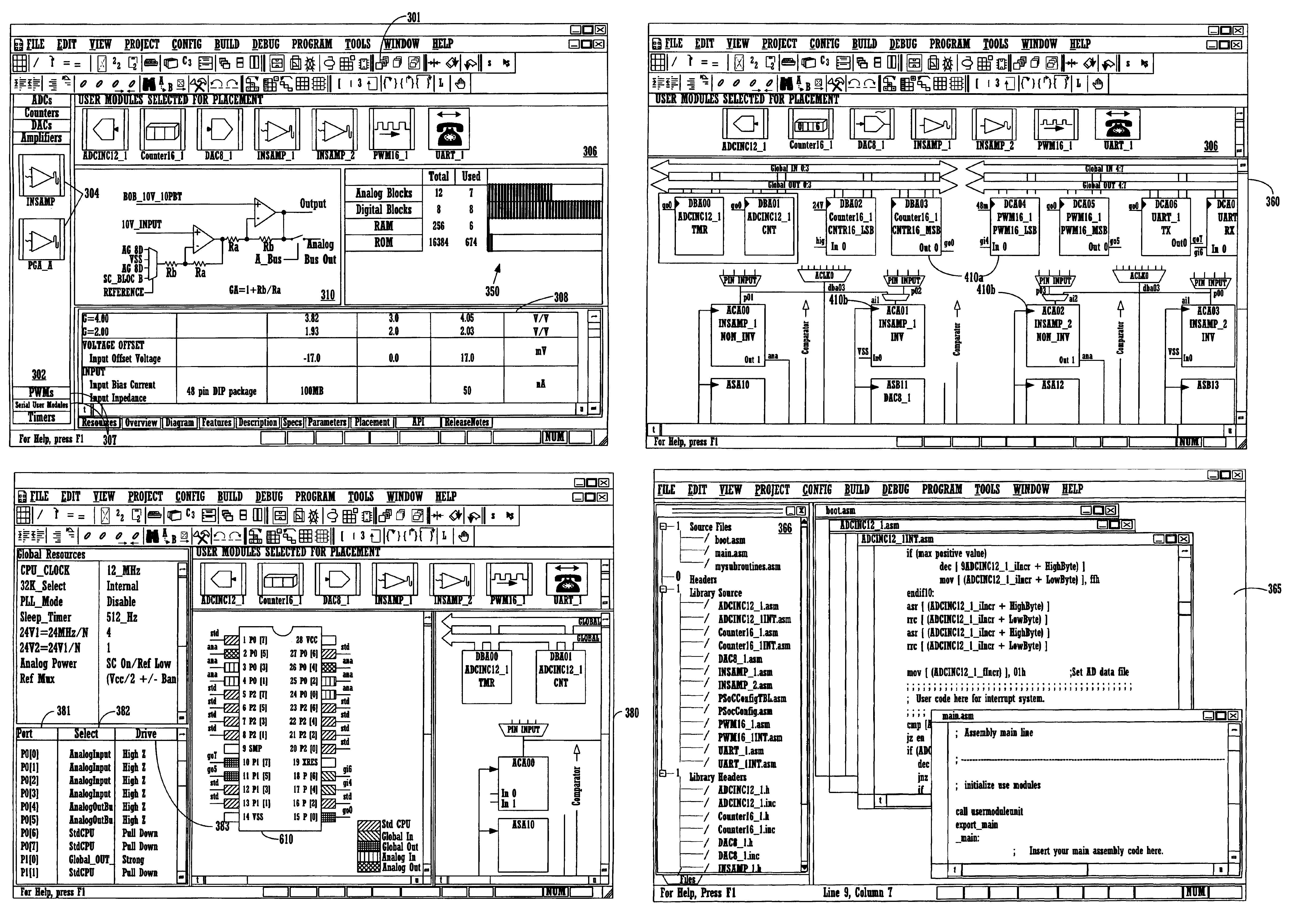
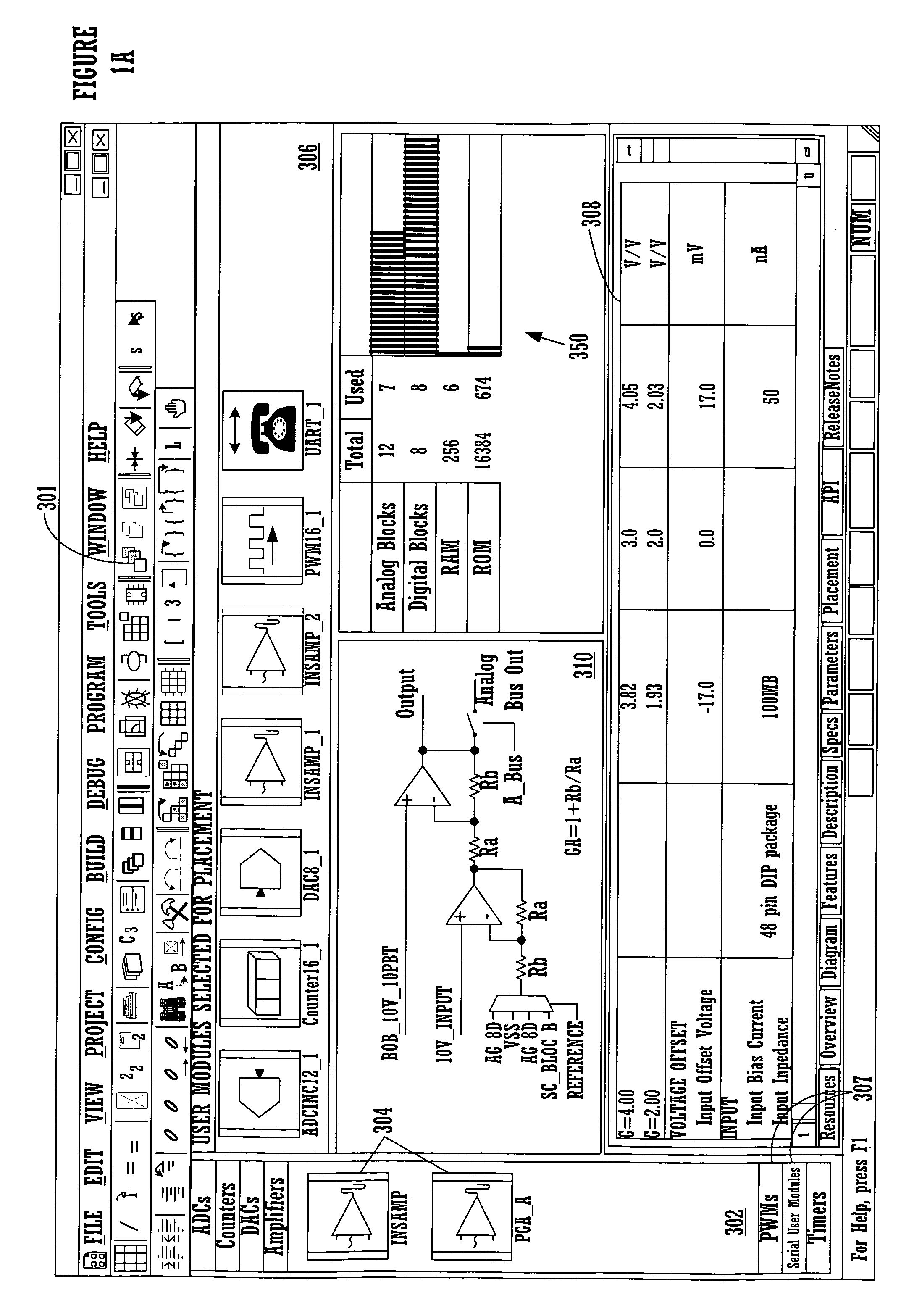
[0025]To facilitate the design process, embodiments provide various work-spaces. For example, a user may move between a user module selection work-space, a user module placement workspace, and a user module pin-out work-space. FIG. 1A illustrates an exemplary graphical user interface which allows a user to select user modules 304. Regarding user module selection, the workspace provides a user module window 302 for a ca...


PUM


Abstract

A method to program a microcontroller using a software program. First a user selects a module from a catalog of available modules. The module may be for implementing an amplifier, timer, pulse width modulator, etc. This causes information related to the selected module to be displayed. For example, a schematic and data sheet for the selected module may be displayed. Next, the user requests a position and places the selected module in a graphical user interface, which represents the resources available to implement the available modules. For example, the resources may be programmable system blocks. Additional user modules may then be selected and placed. The user then configures the circuit by selecting circuit parameters for the user modules (e.g., amplifier gain), pin configurations, and interconnections between programmable system blocks. The user may then edit source code used to cause the user modules to perform their functions.

Description

RELATED APPLICATIONS[0001]This application is related to co-pending, commonly-owned U.S. patent application Ser. No. 09 / 989,570, filed Nov. 19, 2001, entitled “Method for Faciltating Microcontroller Programming,” by Bartz et al.; and to co-pending, commonly-owned U.S. patent application Ser. No. 09 / 989,808, filed Nov. 19, 2001, entitled “Automatic Generation of Application Program Interfaces, Source Code, Interrupts, and Datasheets for Microcontroller Programming,” by Bartz et al.FIELD OF THE INVENTION[0002]The present invention relates to the field of programmable single-chip systems. Specifically, the present invention relates to a method for designing a circuit to be implemented in a target device, such as a microcontroller, using a graphical software program.BACKGROUND ART[0003]Microcontrollers allow circuit designers great flexibility in design choice. However, programming the microcontroller to perform the desired functions can be an arduous task. Conventional software for pro...

Claims


Application Information

Patent Timeline
Patent Type & Authority Patents(United States)
IPC IPC(8): G06F17/50G06F9/45G06F9/455H03K19/00
CPCG06F17/505G06F17/5063G06F17/5054G06F30/36G06F30/34G06F30/327G06F30/347
Inventor BARTZ, MANFREDZHAKSILIKOV, MARATROE, STEVEOGAMI, KENNETH Y.PLEIS, MATTHEW A.ANDERSON, DOUGLAS H.
Owner CYPRESS SEMICON CORP
Why Eureka
Try Eureka