Water pollution trap with water flow baffles

Inactive Publication Date: 2006-03-14
USE CLARK JOSEPH +1
View PDF23 Cites 36 Cited by
  • Summary
  • Abstract
  • Description
  • Claims
  • Application Information

AI Technical Summary

Benefits of technology

[0019]In this exemplary combination embodiment, the screen, baffle, reservoir, and pivotal filter filtration stages cooperate to provide a significant increase in performance over conventional pollution traps. In particular, the screen suspends at least some of the miscellaneous debris above the at-rest water level, the baffles increase water residence time in the chamber to encourage settling of the particulate matter, the collection reservoir skims at least some of the floating matter into it but allows the water to flow under it, and the pivotal filter filters out at least some of the suspended clay. It will be understood by those skilled in the art that these filtration stages can be used in this or other configurations for separating other pollutants from other liquids.
[0020]Accordingly, the pollution trap stays on-line a

Problems solved by technology

Bypassing filtration is a problem because most pollutants are more easily picked up and transported by storm water during higher flow periods.
Unfortunately, just when the traps are needed most, a lot of pollutants bypass them and are delivered into the storm sewer systems.
And most pollution traps that do not provide for bypassing accommodate the larger flows because they are oversized, which adds significantly to the cost to build, install, and maintain th

Method used


Image

  • Water pollution trap with water flow baffles
  • Water pollution trap with water flow baffles
  • Water pollution trap with water flow baffles

Examples


Embodiment Construction

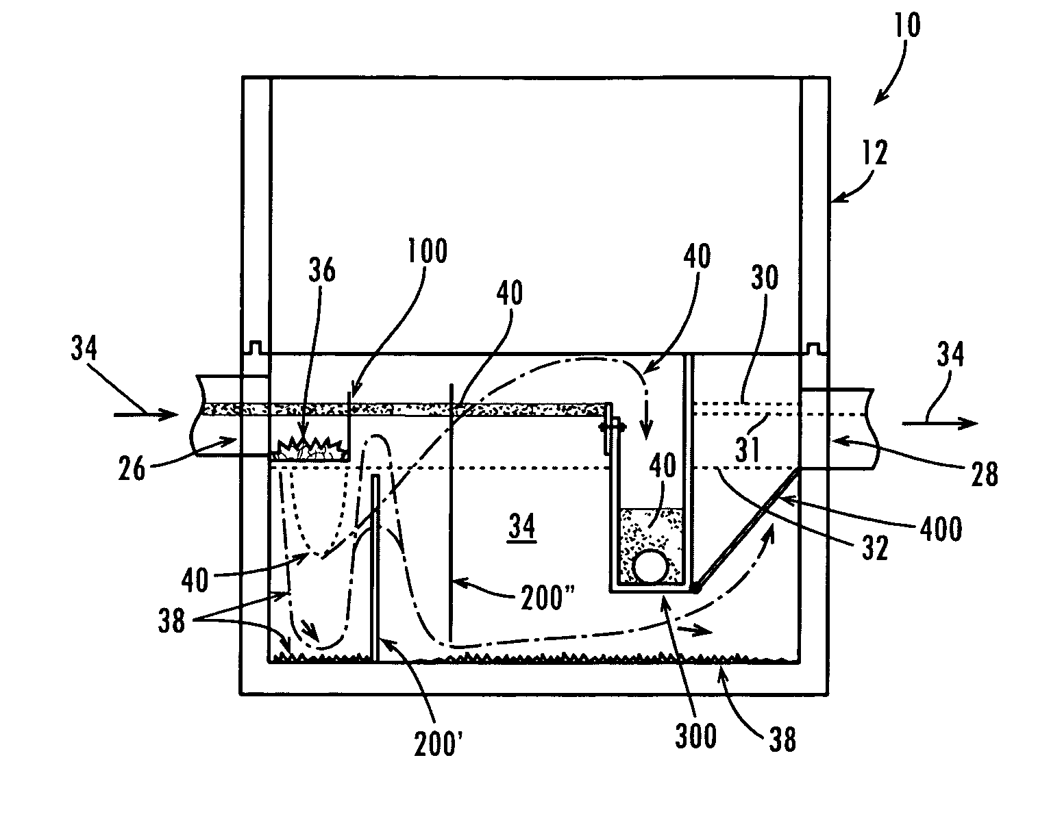
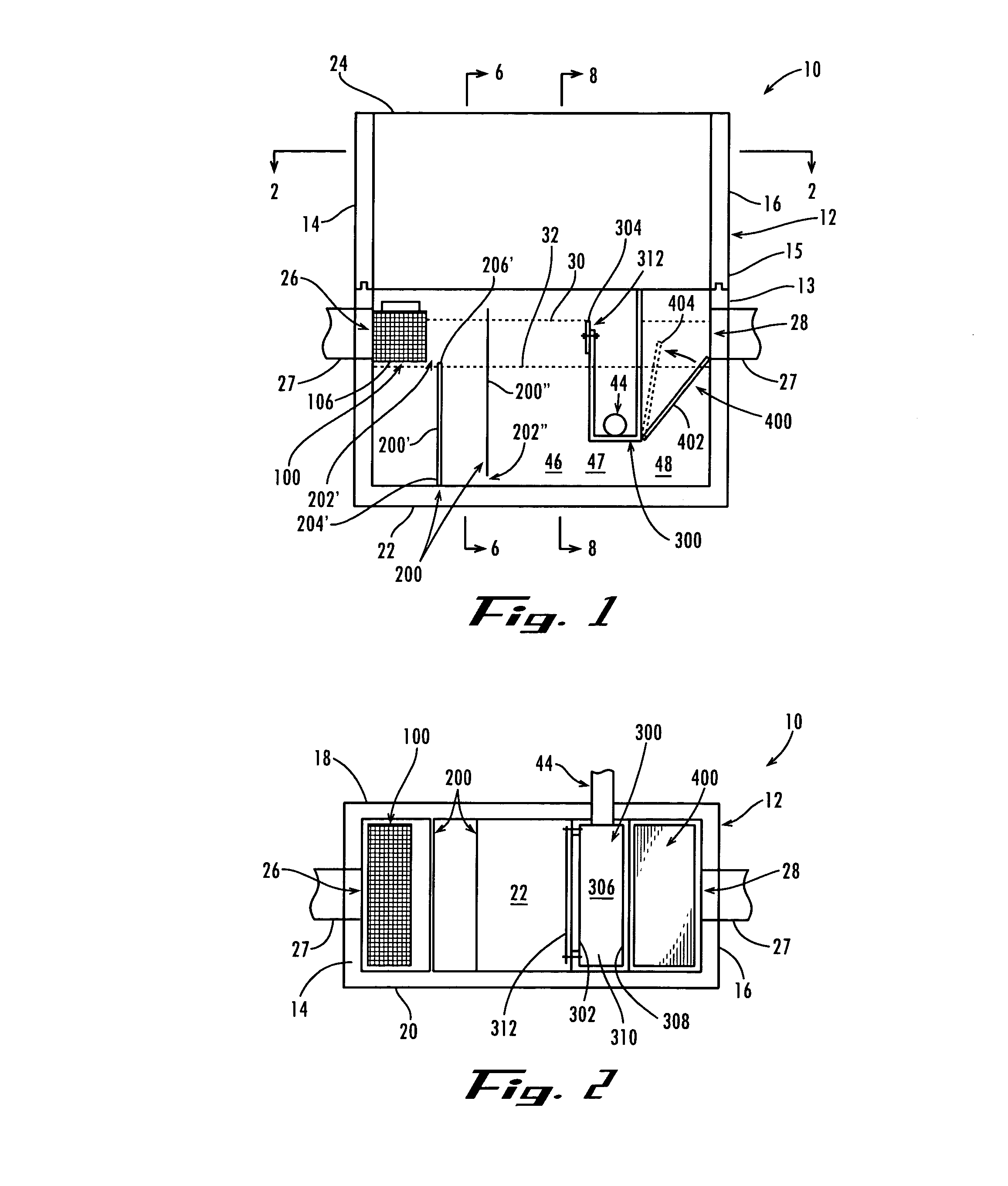
[0053]Referring now to the drawing figures, wherein like reference numerals represent like parts throughout the several views, the pollution trap of the present invention provides for separating pollutants from storm-water runoff and retaining the pollutants in the trap or a nearby storage container. The pollution trap is well suited for filtering pollutants including floatable matter such as motor oil, other hydrocarbons, and detergents, particulate matter such as sand, dirt, and grit, and miscellaneous debris such as vegetative matter from trees, shrubberies, etc., paper and plastic trash, aluminum foil wrappers, foam cups, and so forth. In addition, a person of ordinary skill in the art could adapt the pollution trap described herein in order to separate other types of pollution or other types of matter from liquids other than storm water, if so desired.

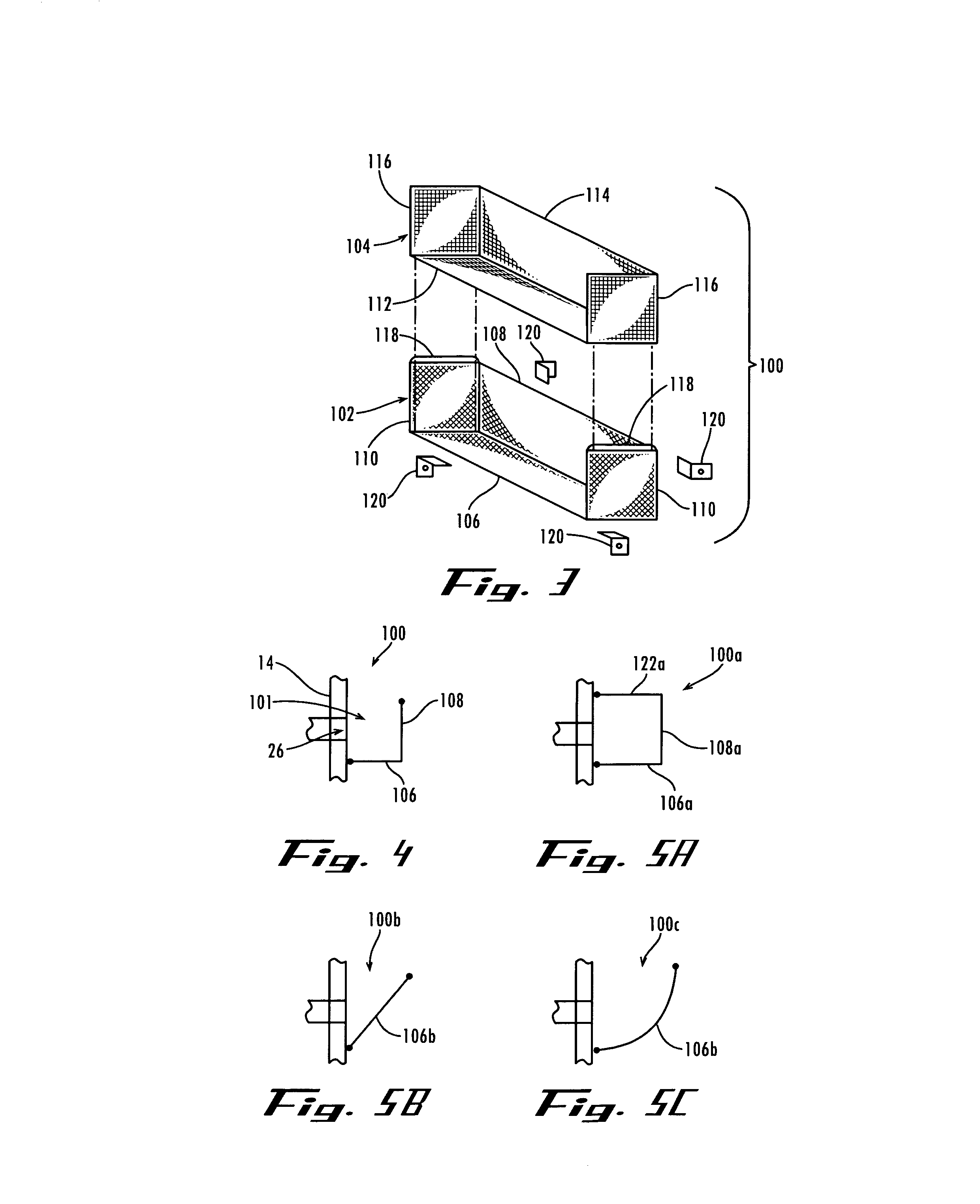
[0054]The pollution trap of the present invention includes one or more baffles for promoting setting of the particular matter po...


PUM

PropertyMeasurementUnit
Flow rateaaaaaaaaaa
Residence timeaaaaaaaaaa

Abstract

A chamber having an inlet for receiving polluted storm-water runoff and an outlet for the storm water to flow out. Within the chamber are one or more baffles forming gaps and having apertures. The gaps define a longer water flow route through the chamber and the apertures disperse the storm water within the chamber. This increases storm-water residence time which encourages settling of particulate matter such as sand and grit. In alternative embodiments, there are included a screen, a collection reservoir, and/or a pivotal filter for further dispersing, detaining, and/or filtering the storm water.

Description

CROSS-REFERENCE TO RELATED APPLICATIONS[0001]This application is a continuation-in-part of U.S. Provisional Patent Application Ser. No. 60 / 345,128, filed Dec. 31, 2001, and U.S. Non-Provisional patent application Ser. No. 10 / 217,186, filed Aug. 12, 2002, now U.S. Pat. No. 6,797,161, which are hereby incorporated herein by reference in its entirety.TECHNICAL FIELD[0002]The present invention relates generally to water pollution traps and, more particularly, to oil / grit separators for separating and collecting various pollutants from storm-water runoff.BACKGROUND OF THE INVENTION[0003]During rainstorms, water that is not absorbed into the ground runs off into storm sewer systems for delivery into freshwater systems such as streams, rivers, lakes, and wetlands. While flowing across parking lots, landscaped areas, and other surfaces, the storm-water runoff picks up debris and pollutants and carries them into the storm sewer systems. Particularly large amounts of pollutants are picked up ...

Claims


Application Information

Patent Timeline
IPC IPC(8): B01D36/04B01D21/00
CPCB01D21/0012B01D21/0033B01D21/0042B01D21/0066B01D21/2433B01D21/245B01D21/0039B01D2221/12B01D2221/08B01D21/0006B01D21/2483
Inventor USE, CLARK JOSEPHMOLL, JOHN SEBASTIAN
Owner USE CLARK JOSEPH
Why Eureka
Try Eureka