Semiconductor chip with passive element in a wiring region of the chip
a technology of semiconductor chip and wiring region, which is applied in the direction of semiconductor device, semiconductor/solid-state device details, electrical apparatus, etc., can solve the problems of inability to increase the number of terminals, the reduction of pitch is subject to fabrication technology limitations, and the inability to use this semiconductor chip, etc., to achieve the effect of increasing the maximum number of external terminals and increasing the cos
- Summary
- Abstract
- Description
- Claims
- Application Information
AI Technical Summary
Benefits of technology
Problems solved by technology
Method used
Image
Examples
first embodiment
[0049]The first embodiment of the present invention will be described below.
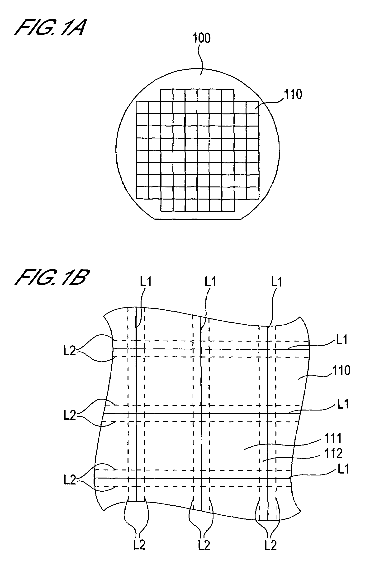
[0050]FIG. 1A is a planar view conceptually showing the structure of a semiconductor wafer according to this embodiment. As shown in FIG. 1A, a wafer 100 comprises a multiplicity of chip regions 110.
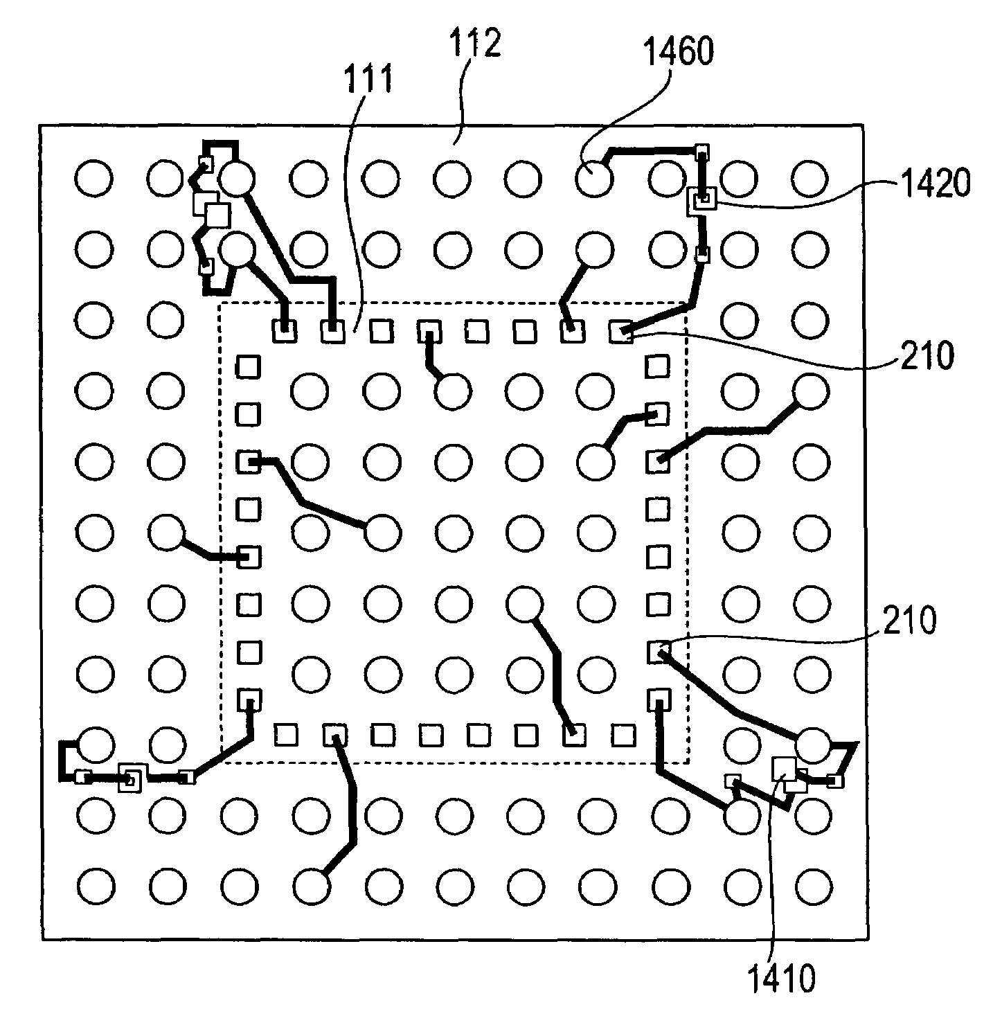
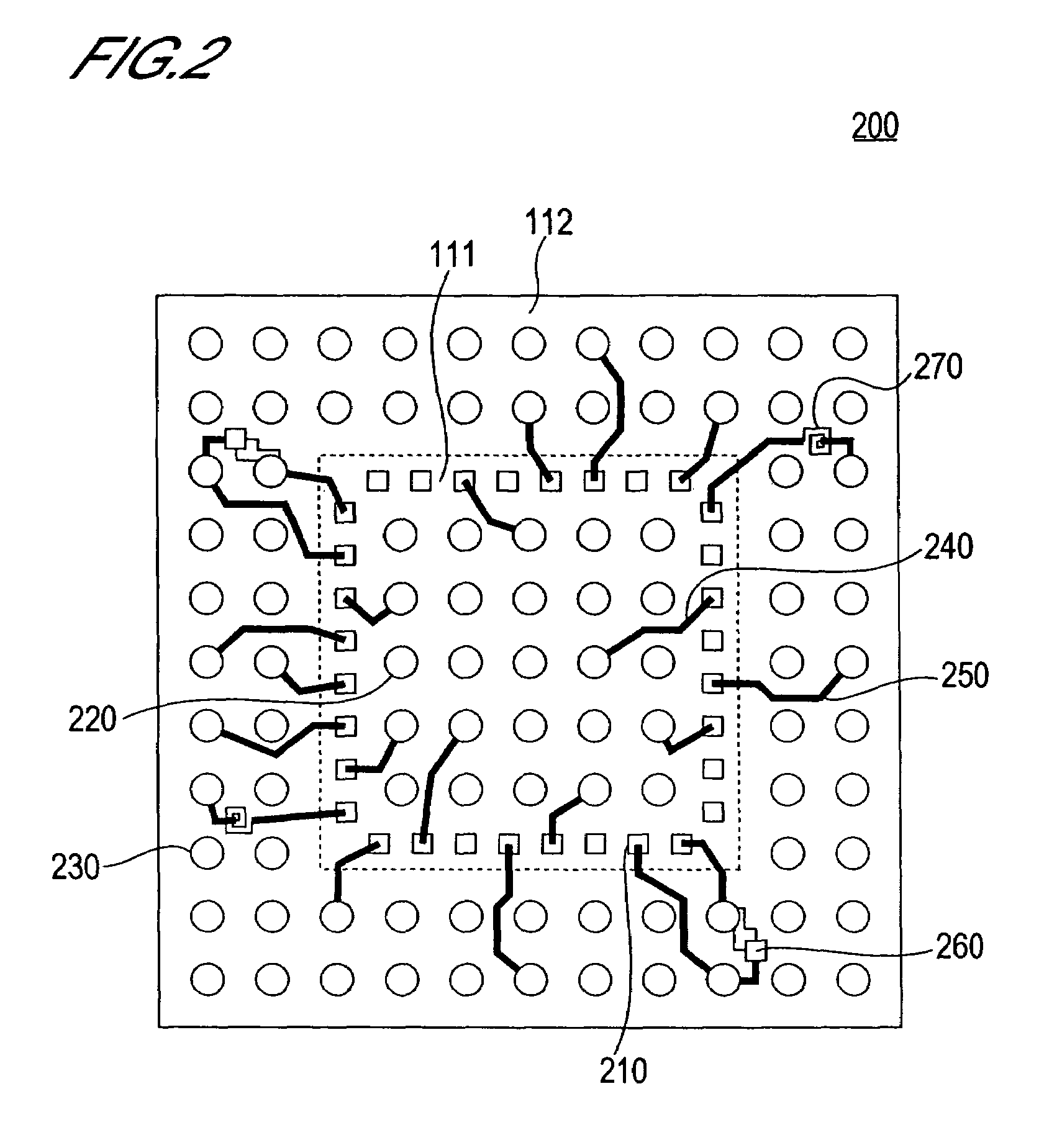
[0051]FIG. 1B is a partial enlarged view of FIG. 1A. In FIG. 1B, the solid lines L1 conceptually show the chip region boundaries. That is, the regions delimited by the lines L1 are the chip regions 110. Each of the chip regions 110 comprises a circuit region 111 and a wiring region 112. In FIG. 1B, the dotted lines L2 conceptually show the boundary between the circuit region 111 and the wiring region 112.
[0052]As will be described below, in the fabrication process for a semiconductor device that has a WCSP structure, the semiconductor wafer 100 is diced along the lines L1. On the other hand, in a fabrication process of a semiconductor device for which a package structure other than a WCSP structure is adopted, th...
second embodiment
[0100]The second embodiment of the present invention will be described next.
[0101]According to the first embodiment described above, a capacitor and an inductor are formed in the redistribution wiring layer (the layer sandwiched between the insulation layers 620 and 630 in FIG. 6). In contrast, the capacitor and inductor are formed below the redistribution wiring layer in the present embodiment.
[0102]The overall constitution of the semiconductor wafer according to this embodiment is the same as that of the semiconductor wafer of the first embodiment (FIGS. 1A and 1B)
[0103]FIG. 13 is a planar view showing the structure below the redistribution wiring layer, of the present embodiment.
[0104]As shown in FIG. 13, the semiconductor chip 1300 of this embodiment comprises the circuit region 111 and the wiring region 112.
[0105]A plurality of electrode pads 210 is provided in the circuit region 111 as per the first embodiment (See FIG. 2).
[0106]Two capacitors 1311, 1312 and two inductors 1321...
third embodiment
[0125]Next, the third embodiment of the present invention will be described.
[0126]The semiconductor device according to this embodiment differs from those of the first and second embodiments above in that the capacitor and inductor are formed in the wiring region 112 in the form of an array.
[0127]FIG. 19 is a planar view conceptually showing the semiconductor chip array formation face according to this embodiment. As shown in FIG. 19, a plurality of capacitors 1910 and a plurality of inductors 1920 are arranged alternately in the wiring region 112, for example. The passive element array is constituted by these capacitors 1910 and inductors 1920. The quantities of the capacitors 1910 and inductors 1920 and the dispositional order thereof, and so forth, can be optionally determined by the designer.
[0128]The capacitors 1910 and inductors 1920 are formed in a layer beneath the redistribution wiring layer as per the second embodiment (See FIGS. 15 and 16).
[0129]The size and characteristi...
PUM
 Abstract
Description
Claims
Application Information
 - R&D
- Intellectual Property
- Life Sciences
- Materials
- Tech Scout
- Unparalleled Data Quality
- Higher Quality Content
- 60% Fewer Hallucinations
Browse by: Latest US Patents, China's latest patents, Technical Efficacy Thesaurus, Application Domain, Technology Topic, Popular Technical Reports.
© 2025 PatSnap. All rights reserved.Legal|Privacy policy|Modern Slavery Act Transparency Statement|Sitemap|About US| Contact US: help@patsnap.com


