Method and apparatus for regulating heat in an asynchronous system

a technology of asynchronous circuits and heat buildup, applied in the field of systems, can solve the problems of circuits switching more frequently, affecting the performance of computational circuits, and becoming progressively harder to synchronize computational operations with reference to a single global clock signal, so as to achieve less hea

Inactive Publication Date: 2006-03-14
ORACLE INT CORP +1
View PDF15 Cites 17 Cited by
  • Summary
  • Abstract
  • Description
  • Claims
  • Application Information

AI Technical Summary

Benefits of technology

[0009]One embodiment of the present invention provides a system that regulates heat within an asynchronous circuit. During operation, the system monitors a temperature within the asynchronous circuit. If the temperature exceeds a threshold value, the system introduces a delay into the asynchronous circuit that causes signals to propagate more slowly through the asynchronous circuit. This causes circuit elements within the asynchronous circuit to switch less frequently and consequently causes the circuit elements to generate less heat.

Problems solved by technology

However, as computational operations are performed more rapidly and involve increasingly larger amounts of computational circuitry, it is becoming progressively harder to synchronize computational operations with reference to a single global clock signal.
In many cases, enforcing such synchronization greatly constrains the performance of the computational circuitry.
However, increasing the computational speed of an asynchronous circuit causes the circuit to switch more frequently.
This increases power consumption and consequently generates a significant amount of heat.
However, as the computational speed of semiconductor chips continues to increase, and as these chips are packed more closely together to minimize propagation delay between the chips, it is becoming progressively harder to effectively dissipate this heat.
This leads to excessive heat buildup, which can cause a computer system to fail, and in some cases can permanently damage circuitry within the computer system.
If the temperature exceeds a threshold value, the system introduces a delay into the asynchronous circuit that causes signals to propagate more slowly through the asynchronous circuit.

Method used


Image

  • Method and apparatus for regulating heat in an asynchronous system
  • Method and apparatus for regulating heat in an asynchronous system
  • Method and apparatus for regulating heat in an asynchronous system

Examples


Embodiment Construction

[0021]The following description is presented to enable any person skilled in the art to make and use the invention, and is provided in the context of a particular application and its requirements. Various modifications to the disclosed embodiments will be readily apparent to those skilled in the art, and the general principles defined herein may be applied to other embodiments and applications without departing from the spirit and scope of the present invention. Thus, the present invention is not intended to be limited to the embodiments shown, but is to be accorded the widest scope consistent with the principles and features disclosed herein.

Temperature Regulation System

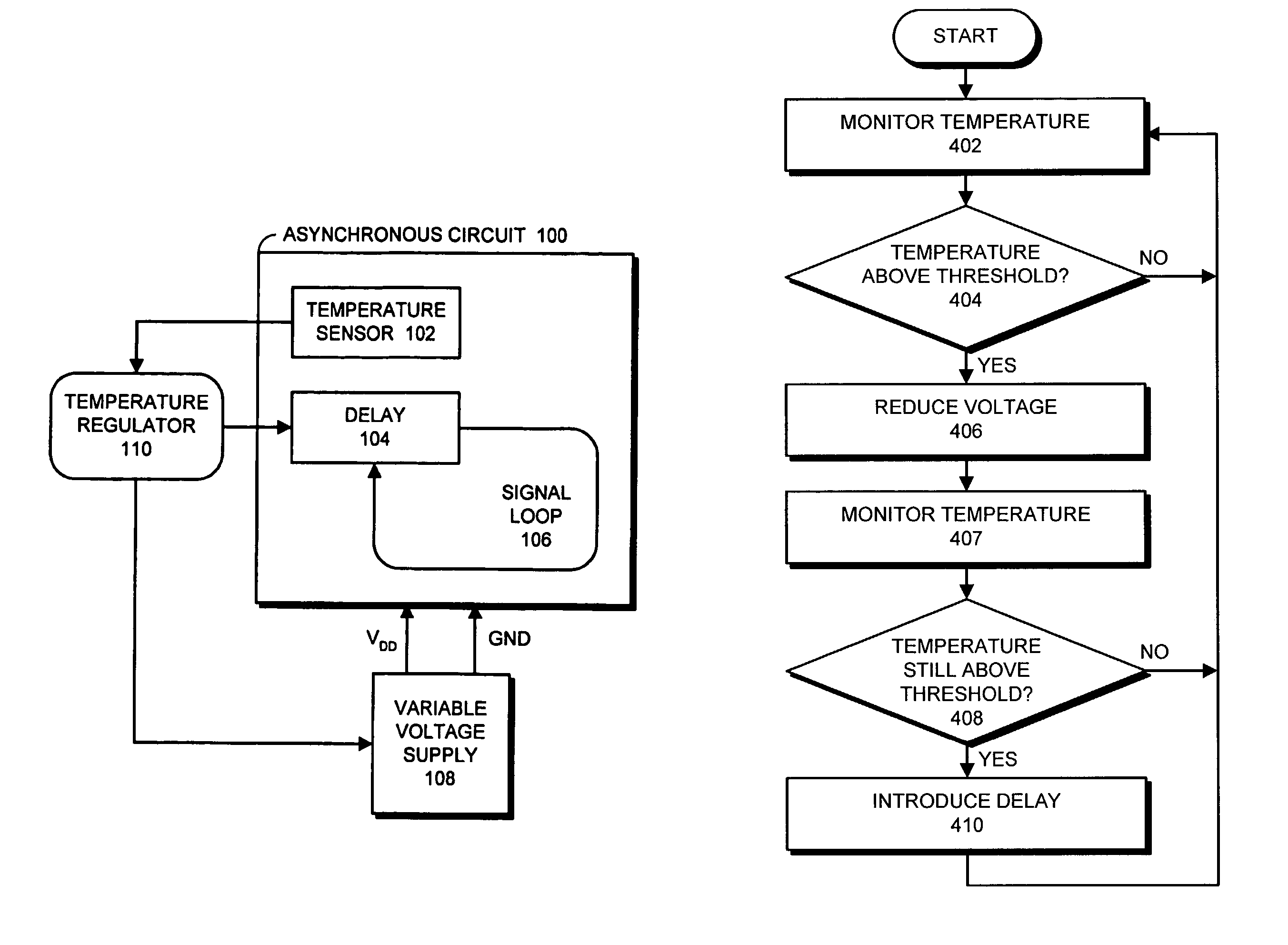
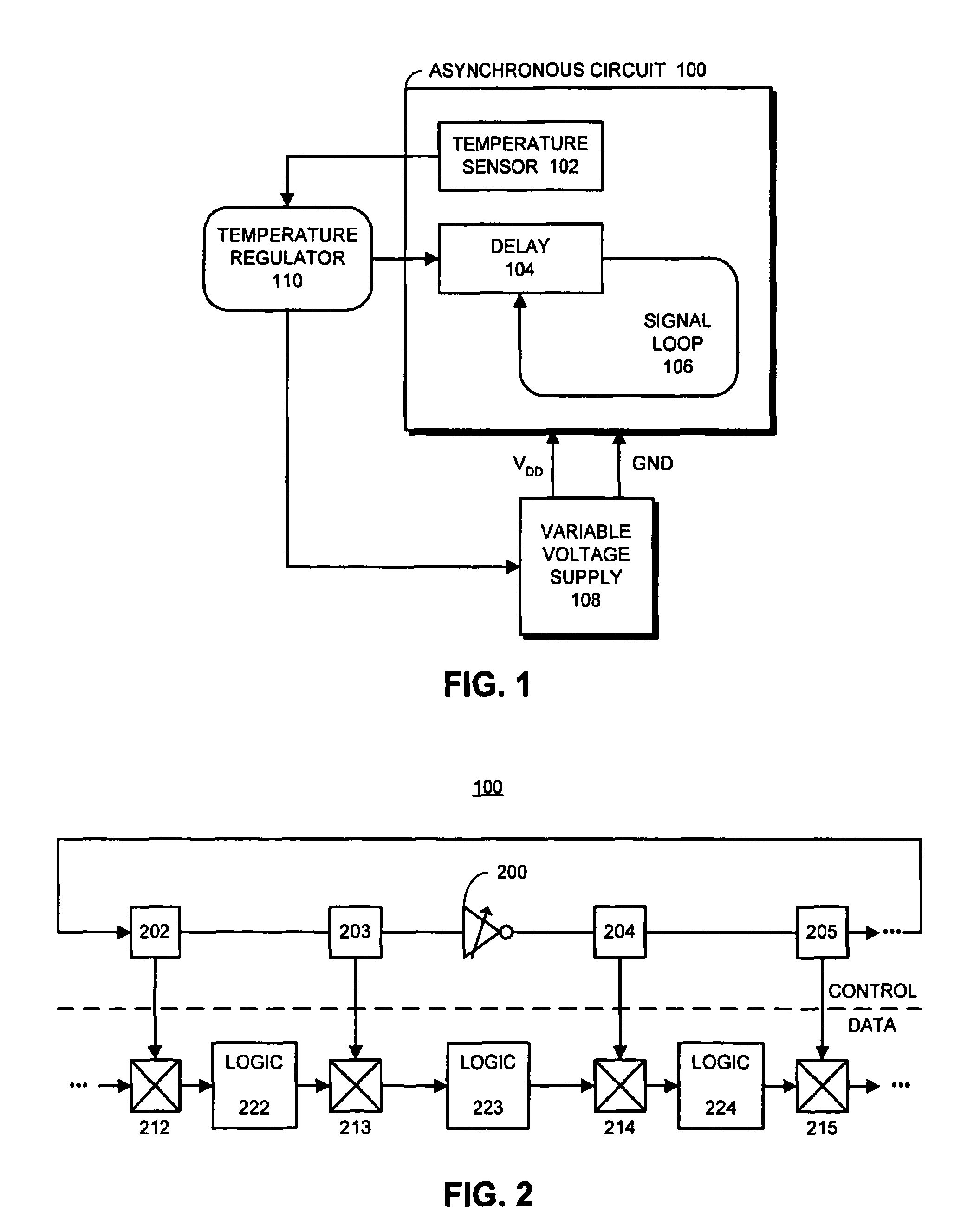
[0022]FIG. 1 illustrates a temperature regulation system for an asynchronous circuit 100 in accordance with an embodiment of the present invention. The asynchronous circuit illustrated in FIG. 1 can generally include any type of circuit that does not synchronize computational operations and data movement operations ...


PUM


Abstract

One embodiment of the present invention provides a system that regulates heat within an asynchronous circuit. During operation, the system monitors a temperature within the asynchronous circuit. If the temperature exceeds a threshold value, the system introduces a delay into the asynchronous circuit that causes signals to propagate more slowly through the asynchronous circuit. This causes circuit elements within the asynchronous circuit to switch less frequently and consequently causes the circuit elements to generate less heat.

Description

[0001]This application is a continuation of, and hereby claims priority under 35 U.S.C. § 120 to, abandoned U.S. patent application Ser. No. 10 / 406,298, filed Apr. 02, 2003, entitled “Method and System for Regulating Heat in an Asynchronous System” by inventor Ivan B. Sutherland.BACKGROUND[0002]1. Field of the Invention[0003]The present invention relates to the design of systems that regulate the buildup of heat within electrical circuitry. More specifically, the present invention relates to a method and an apparatus for regulating the buildup of heat within an asynchronous circuit.[0004]2. Related Art[0005]The dramatic increases in computational speed in recent years have largely been facilitated by improvements in semiconductor integration densities, which presently allow hundreds of millions of transistors to be integrated into a single semiconductor chip. This makes it possible to incorporate a large amount of computational circuitry onto a semiconductor chip. Moreover, the smal...

Claims


Application Information

Patent Timeline
Patent Type & Authority Patents(United States)
IPC IPC(8): H03K17/14G05D23/00G05D23/19
CPCG05D23/1951
Inventor SUTHERLAND, IVAN E.
Owner ORACLE INT CORP
Why Eureka
Try Eureka