Duplexer, and laminate-type high-frequency device and communication equipment using the same

a high-frequency device and laminate-type technology, applied in coupling devices, electrical devices, waveguides, etc., can solve the problems of reducing the degree of design freedom, increasing the loss of branching circuits, and increasing the layout space, so as to reduce the loss, simplify the configuration, and reduce the effect of loss

Inactive Publication Date: 2006-03-14
PANASONIC CORP
View PDF13 Cites 9 Cited by
  • Summary
  • Abstract
  • Description
  • Claims
  • Application Information

AI Technical Summary

Benefits of technology

[0019]Therefore, with the foregoing in mind, it is an object of the present invention to provide a duplexer that can be realized with a very simple configuration, designed so as to substantially reduce a loss, and miniaturized easily, and a laminate-type high-frequency device and communication equipment using the duplexer. Furthermore, it is another object of the present invention to provide a duplexer that is improved so as to obtain a sufficient degree of design freedom, and a laminate-type high-frequency device and communication equipment using the duplexer.

Problems solved by technology

However, in the above-mentioned configuration, the circuit configuration is complicated, so that a loss in the branching circuit is increased, and the layout space is necessarily increased.
Furthermore, it is difficult to obtain a large L-value in the inductor connected in parallel with two filters, respectively, so that the degree of design freedom is lowered.

Method used


Image

  • Duplexer, and laminate-type high-frequency device and communication equipment using the same
  • Duplexer, and laminate-type high-frequency device and communication equipment using the same
  • Duplexer, and laminate-type high-frequency device and communication equipment using the same

Examples


embodiment 1

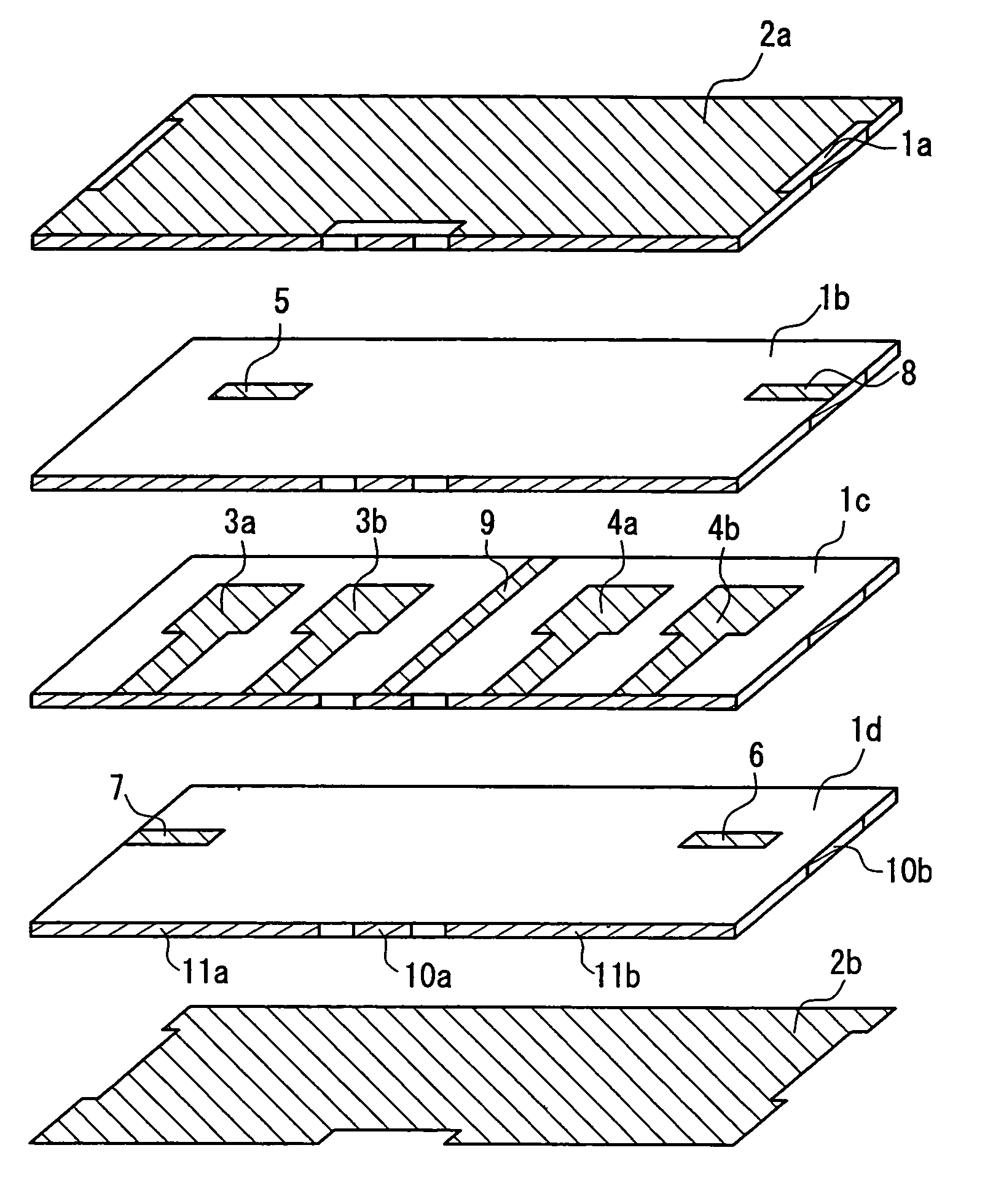
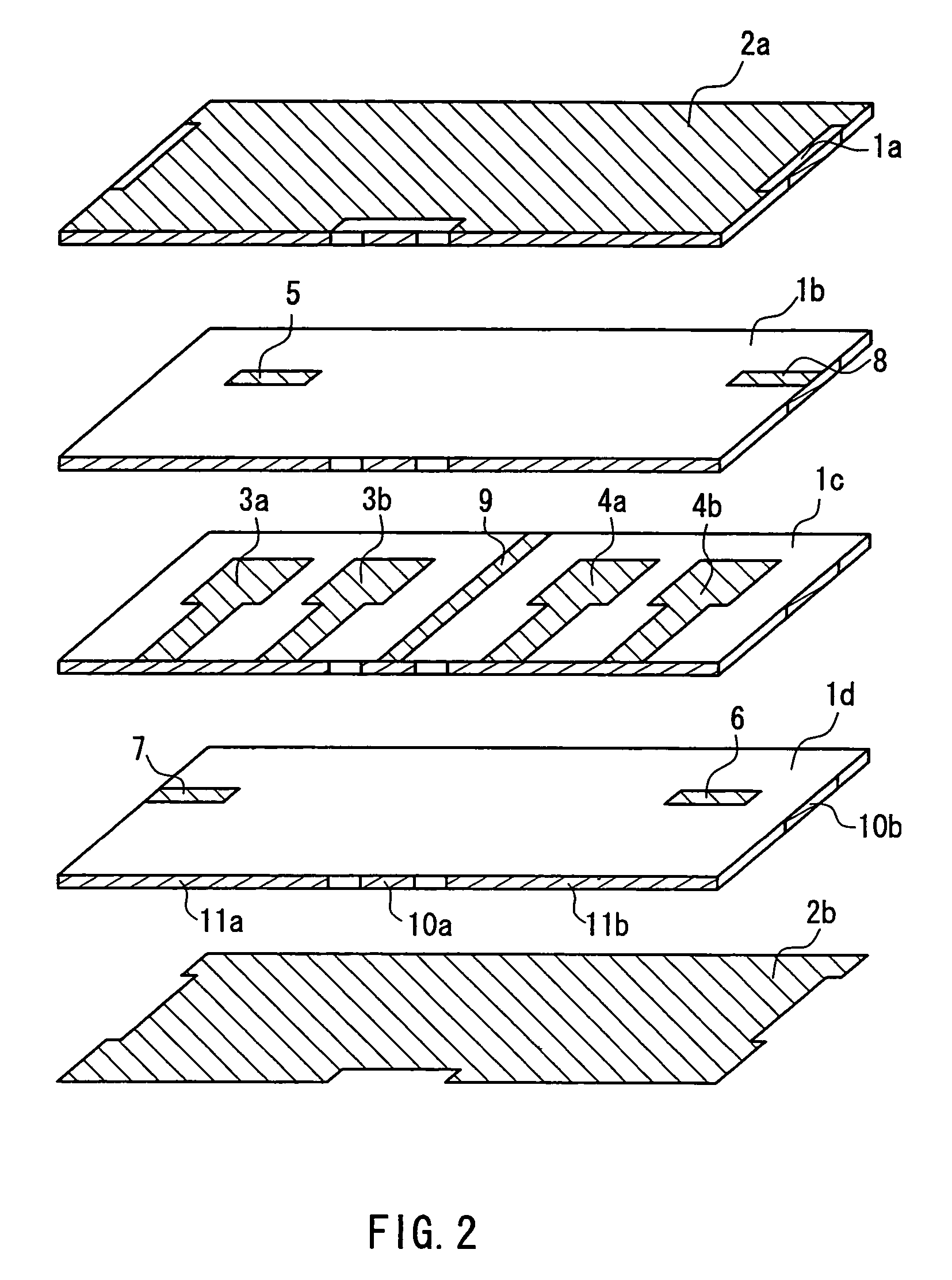
[0092]FIG. 2 is an exploded perspective view showing a duplexer according to Embodiment 1 of the present invention.

[0093]As shown in FIG. 2, the duplexer according to the present embodiment is composed of a laminate in which dielectric layers and electrode layers are laminated alternately. In the laminate, a first filter for transmitting and a second filter for receiving, having different pass band frequencies, are provided. Furthermore, a matching circuit composed of a coupling line 9, having one end that is short-circuited and the other end that is connected to an external terminal, is provided between the first filter and the second filter.

[0094]The first filter includes two first stripline resonators 3a and 3b, each having one end that is short-circuited. The second filter includes two second stripline resonators 4a and 4b, each having one end that is short-circuited. The coupling line 9 is coupled to the first stripline resonator 3b close to the coupling line 9 by electromagnet...

embodiment 2

[0106]FIG. 6 is an exploded perspective view showing a duplexer according to Embodiment 2 of the present invention. The duplexer according to the present embodiment is the same as that according to Embodiment 1 except for the points described below. Therefore, like components are denoted with like numerals, and their description will be omitted here.

[0107]As shown in FIG. 6, in the duplexer according to the present embodiment, the first stripline resonators 3a, 3b and the second stripline resonators 4a, 4b are formed on dielectric layers 1c, 1e, different from the dielectric layer 1d on which the coupling line 9 is formed. Thus, by forming the first stripline resonators 3a, 3b and the second stripline resonators 4a, 4b on the dielectric layers 1c, 1e different from the dielectric layer 1d on which the coupling line 9 is formed, the degree of design freedom and versatility can be provided.

[0108]Furthermore, the coupling line 9 is composed of two striplines (wide portion and narrow po...

embodiment 3

[0111]FIG. 7 is an exploded perspective view showing a duplexer according to Embodiment 3 of the present invention. The duplexer according to the present embodiment is the same as that according to Embodiment 2 except for the points described below. Therefore, like components are denoted with like numerals, and their description will be omitted here.

[0112]As shown in FIG. 7, in the duplexer according to the present embodiment, the coupling line is composed of three striplines 9a, 9b, and 9c, and the three striplines 9a, 9b, and 9c are provided on different dielectric layers 1c, 1d, and 1e, respectively. In the case where there is only one stripline, an electric potential is fluctuated. However, by using three striplines, the electric potential can be stabilized.

[0113]It is desirable that at least one of the three striplines 9a, 9b, and 9c has a line width different from those of the others. In the present embodiment, all the striplines 9a, 9b, and 9c are configured so as to have dif...


PUM


Abstract

A duplexer is composed of a laminate in which dielectric layers and electrode layers are laminated alternately. A first filter for transmitting and a second filter for receiving, having different pass band frequencies, are provided in the laminate. A matching circuit composed of a coupling line, having one end that is short-circuited and the other end that is connected to an external terminal, is provided between the first filter and the second filter. The first filter includes two first stripline resonators, each having one end that is short-circuited. The second filter includes two second stripline resonators, each having one end that is short-circuited. The coupling line is coupled to the first stripline resonator dose to the coupling line by electromagnetic field coupling. The coupling line is coupled to the second stripline resonator close to the coupling line by electromagnetic coupling.

Description

BACKGROUND OF THE INVENTION[0001]1. Field of the Invention[0002]The present invention relates to a duplexer, and a laminate-type high-frequency device and communication equipment provided with the duplexer. More specifically, the present invention relates to an antenna duplexer sharing one antenna on a transmitting side and a receiving side and separating a transmitted signal and a received signal from each other, and a laminate-type high-frequency device and communication equipment provided with the antenna duplexer.[0003]2. Description of the Related Art[0004]In an antenna duplexer sharing one antenna on a transmitting side and a receiving side, and separating a transmitted signal and a received signal from each other, two filters having different center frequencies are connected. Therefore, it is required that, at a center frequency of one of the two filters, the impedance of the other filter seen from an antenna that is an input / output terminal shared by the two filters is set t...

Claims


Application Information

Patent Timeline
Patent Type & Authority Patents(United States)
IPC IPC(8): H01P1/213H01P1/203
CPCH01P1/2135
Inventor MAEKAWA, TOMOYASHIGEMURA, HIROSHI
Owner PANASONIC CORP
Why Eureka
Try Eureka