Switchable permanent magnetic device

a permanent magnet, switchable technology, applied in the direction of magnets, magnet bodies, manufacturing tools, etc., can solve the problems of fixed energy output, inability to use, complexity and potential hazards, and achieve the effect of improving properties

Inactive Publication Date: 2006-03-14
MAGSWITCH TECH
View PDF36 Cites 101 Cited by
  • Summary
  • Abstract
  • Description
  • Claims
  • Application Information

AI Technical Summary

Benefits of technology

[0009]It is an object of the present invention to provide a switchable magnetic device having improved properties.
[0018]The housing most preferably comprises a pair of passive poles. The strength of the external magnetic field can be maximised by shaping the pair of passive poles such that they reflect the magnetic field strength around the perimeter of the first and second permanent magnets.
[0023]As mentioned earlier, it is preferred that one magnet is fixed in the housing and one magnet can rotate in the housing. It is especially preferred that the rotatable magnet can rotate about the centre point of its essentially circular faces. In this fashion, the requirement for large clearances between the inner walls of the housing and the rotatable magnet are avoided. In this embodiment, the shape of the body of rotation of the rotatable magnet is the same shape as the magnet itself (ie substantially circular in top or plan view) and thus the magnet can rotate and yet retain its positioning relative to the walls of the housing.

Problems solved by technology

However, permanent magnets suffer from the drawback that their energy output is fixed and they cannot be employed if a variation in magnetic field strength is required.
Due to the above-mentioned drawback with permanent magnets, it has been customary to control magnetic fields by using electric currents or electromagnets.
This can cause complexity and potential hazards.
However, these approaches resulted in bulky constructions, complicated constructions, or devices that were expensive to manufacture.
The prior art devices also paid little attention to achieving a good holding force between the devices and substrates under conditions where an incomplete external magnetic circuit existed, for example, where there were gaps between the magnet and the keeper, or where the keeper or substrate had a low permeability, such as thin ferrous sheet metal.
This, of course, could be difficult to achieve in practice.

Method used


Image

  • Switchable permanent magnetic device
  • Switchable permanent magnetic device
  • Switchable permanent magnetic device

Examples


Embodiment Construction

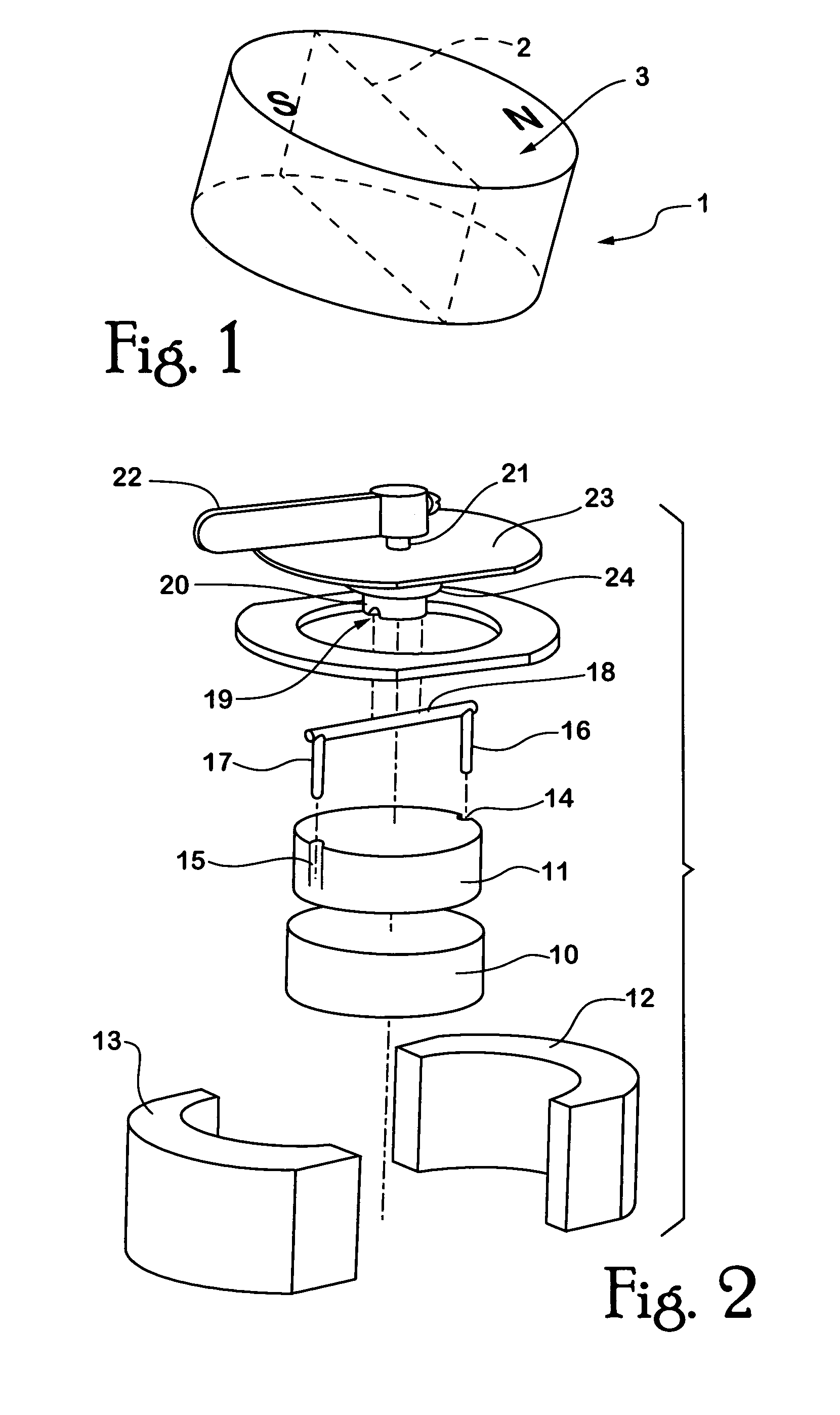
[0060]The magnet 1 as shown in FIG. 1 may be described as a cylindrically-shaped magnet. The magnet is diametrically magnetised. By that, is meant that the notional division between the north pole and the south pole of the magnet is achieved by a vertical plane that passes along a diameter 2 of an upper face 3 of the disc magnet 1.

[0061]The disc magnet 1 shown in FIG. 1 is preferably a rare-earth type magnet, for example, the magnet 1 may be a neodymium-iron-boron magnet. The present invention also contemplates the use of any other permanent magnet material.

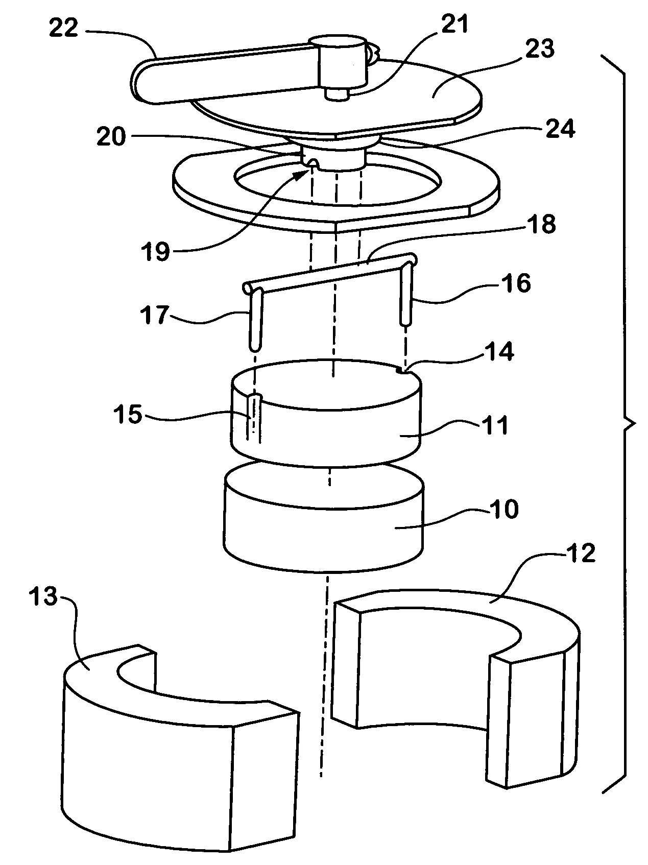
[0062]Turning to FIG. 2, the device includes a first magnet 10 and a second magnet 11. Both magnets 10, 11 are essentially disc shaped magnets and are similar to magnet 1 as shown in FIG. 1. Magnets 10, 11 are housed in a housing that is made from pole pieces 12, 13. Pole pieces 12, 13 are preferably made from a material that is ferromagnetic with low magnetic reluctance. The pole pieces 12, 13 are arranged such that they fixedly...


PUM

PropertyMeasurementUnit
angle of rotationaaaaaaaaaa
angle α1aaaaaaaaaa
external magnetic fieldaaaaaaaaaa

Abstract

A switchable magnetic device includes a first magnet and a second magnet, both of which are essentially cylindrical. Magnets are housed in a housing made from pole pieces. Pole pieces are ferromagnetic. Lower magnet is fixedly mounted in the housing while upper magnet can rotate within the housing. Upper magnet is formed with notches or grooves along its vertical side walls. These notches or grooves receive downwardly depending arms of bar. Bar is received inside a groove formed on boss. Boss is connected to a short bar that, in turn, is fixedly connected to a handle or lever. By this means, rotation of handle or lever causes rotation of second magnet. When the upper magnet is positioned such that its north pole substantially overlies the south pole of lower magnet and the south pole of upper magnet substantially overlies the north pole of lower magnet, the first and second magnets act as an internal active magnetic shunt and as a result the external magnetic field strength from the device is quite low. Rotating the upper magnet 180° about its axis of rotation brings the magnets into alignment such that the respective north and south poles of the upper magnet substantially overlie respective north and south poles of lower magnet. In this alignment, the external magnet field from the device is quite strong and the device can be affixed to surfaces or objects.

Description

CROSS REFERENCE TO RELATED APPLICATIONS[0001]This application is a continuation of application Ser. No. 09 / 951,905, filed Sep. 14, 2001, and issued as U.S. Pat. No. 6,707,360, which is a Continuation-In-Part of International Application PCT / AU00 / 01505, filed Dec. 6, 2000, which claims priority to Australian Application PO4466, filed Dec. 6, 1999, the contents of which are all incorporated by reference.FIELD OF THE INVENTION[0002]The present invention relates to a magnetic device. In particular, the present invention relates to a switchable permanent magnet device.BACKGROUND OF THE INVENTION[0003]Permanent magnets consist of a ferromagnetic material that has been suitably magnetized. Permanent magnets provide a magnetic field without requiring an electric current. Permanent magnets are attracted to and can be firmly affixed ferromagnetic materials. However, permanent magnets suffer from the drawback that their energy output is fixed and they cannot be employed if a variation in magne...

Claims


Application Information

Patent Timeline
Patent Type & Authority Patents(United States)
IPC IPC(8): H01F7/02B23Q3/154H01F7/04
CPCB23Q3/1546H01F7/04H01F7/0226H01F7/0257H01F7/122
Inventor UNDERWOOD, PERRY JKOCIJAN, FRANZ
Owner MAGSWITCH TECH
Why Eureka
Try Eureka