Method and apparatus for controlling reproduction of optical recording medium

a technology of optical recording medium and control method, which is applied in the direction of digital signal error detection/correction, recording signal processing, instruments, etc., can solve the problems of difficult land/groove discrimination, tracking error signal cannot be obtained through the 2-divided optical detector, and tracking error signal cannot be detected through the pp method

Inactive Publication Date: 2006-03-14
IONOSEP X HLDG
View PDF13 Cites 14 Cited by
  • Summary
  • Abstract
  • Description
  • Claims
  • Application Information

AI Technical Summary

Benefits of technology

[0033]Accordingly, the present invention is directed to a method and apparatus for controlling reproduction of an optical recording medium that substantially obviates one or more problems due to limitations and disadvantages of the related art.

Problems solved by technology

In other words, since the incident light and the reflected light are offset due to an interference therebetween if the depth of the pit is λ / 4, the tracking error signal cannot be obtained through the 2-divided optical detector.
Specifically, since the depth of the pit is λ / 4 in case of the DVD-ROM, the tracking error signal cannot be detected through the PP method.
However, if the RC is too small to be detected, i.e., if it is difficult to secure the RC due to the high-density and high-speed operation and the mirror is not properly detected as well, it becomes difficult to perform the land / groove discrimination and also an automatic breaking system does not operate.
This causes the servo to be unstable during the track-on.

Method used


Image

  • Method and apparatus for controlling reproduction of optical recording medium
  • Method and apparatus for controlling reproduction of optical recording medium
  • Method and apparatus for controlling reproduction of optical recording medium

Examples


Embodiment Construction

[0058]Reference will now be made in detail to the preferred embodiments of the present invention, examples of which are illustrated in the accompanying drawings.

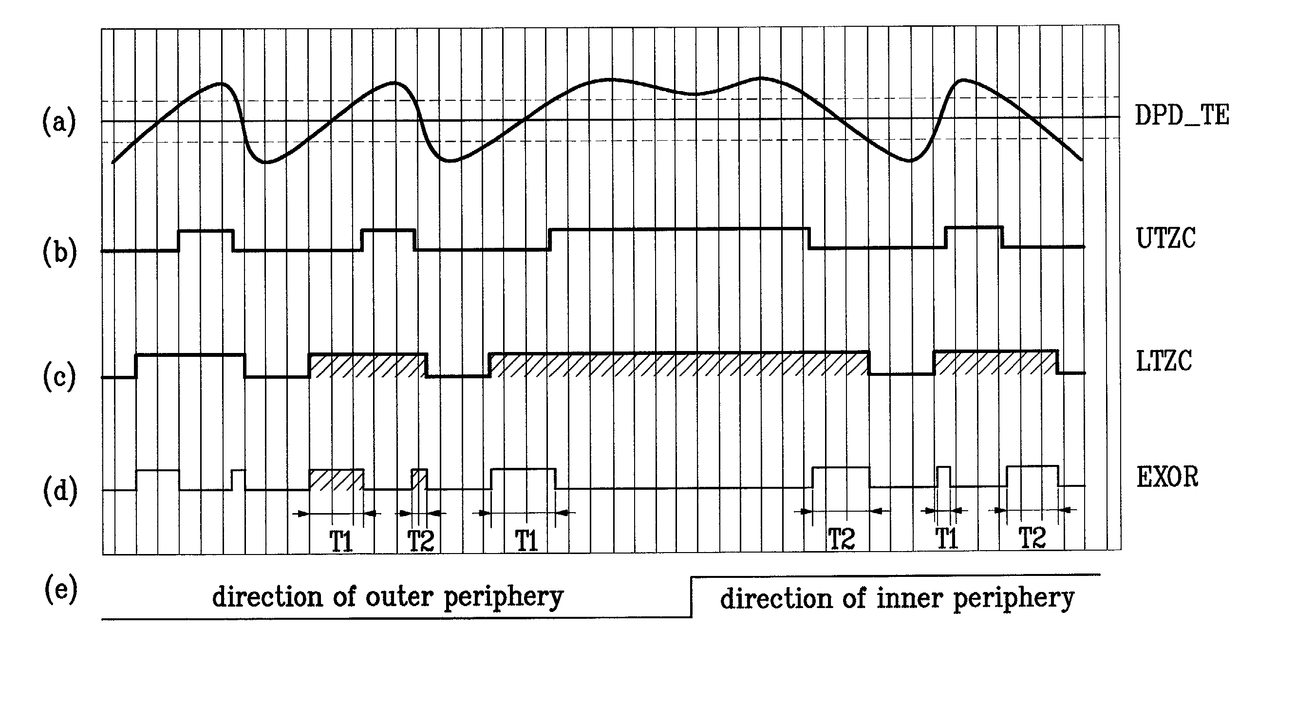
[0059]Typically, as an optical beam passes a pit line (i.e., groove track) or a land having no pit (i.e., mirror), the corresponding variations of phase difference of a DPD error signal are quite different from each other. Specifically, when the optical beam passes the pit line, the phase slope of a diagonal component is slow based on an RF signal, while when the optical beam passes the mirror (or land) region, the phase variation of the diagonal component becomes great to vary the slope abruptly. Accordingly, the center of the pit line is a position most suitable for operating a track servo.

[0060]According to the present invention, the direction of an object lens is detected by obtaining the slope of the DPD error signal, and the track control is performed using the direction of the object lens.

[0061]FIG. 4 is a block diagr...


PUM

PropertyMeasurementUnit
differential phase detectionaaaaaaaaaa
timeaaaaaaaaaa
pulse widthaaaaaaaaaa

Abstract

A method and apparatus for controlling reproduction of an optical recording medium is disclosed. According to the method and apparatus, a moving direction of an object lens on a disc is detected from a slope of a differential phase detection (DPD) error signal in case that the tracking control of the disc is performed by the DPD error signal, and the tracking control is performed using the detected moving direction of the object lens. Thus, the proceeding direction of the object lens can be easily and accurately detected in the disc from which the detection of a mirror signal is not facilitated, i.e., in the disc whose tracking is controlled by the DPD error signal during reproduction. Since it can be easily discriminated whether the phase of the tracking error signal to be in a track-on state when a track servo is turned on is a land or a groove, the stability of the servo can be secured, and an automatic breaking can be achieved.

Description

CROSS REFERENCE TO RELATED ART[0001]This application claims the benefit of Korean Patent Application No. 2000-0057907, filed on Oct. 2, 2000, the contents of which is hereby incorporated by reference in its entirety.BACKGROUND OF THE INVENTION[0002]1. Field of the Invention[0003]The present invention generally relates to an optical recording medium system, and more particularly, to a method and apparatus for controlling reproduction of an optical recording medium that generates a servo control signal by detecting the direction of an object lens in a high-density optical recording medium.[0004]2. Background of the Related Art[0005]Generally, an optical disc recording / reproducing apparatus is an apparatus for recording / reproducing data on / from an optical recording medium, i.e., optical disc such as a compact disc (CD), digital versatile disc (DVD), etc.[0006]At this time, as rewritable digital versatile discs, there exist a rewritable DVD (DVD-RW), recordable DVD (DVD-R), DVD-RAM, etc...

Claims


Application Information

Patent Timeline
Patent Type & Authority Patents(United States)
IPC IPC(8): G11B7/095G11B7/007G11B19/02G11B7/085G11B7/09
CPCG11B7/00718G11B7/0901G11B7/08517G11B19/02
Inventor PARK, SANG ON
Owner IONOSEP X HLDG
Why Eureka
Try Eureka