
Optical recording medium and optical recording process using the same

a technology of optical recording medium and optical recording process, which is applied in the field of optical recording medium, can solve the problems of overwriting distortion, noise at reproducing signals, and disadvantages of having a large value of ac/aa, and achieve the effects of improving the repetitive recording properties of light-transmittance optical recording medium, double the recording capacity, and improving the repetitive recording properties

Inactive Publication Date: 2006-03-14
RICOH KK
View PDF18 Cites 63 Cited by
  • Summary
  • Abstract
  • Description
  • Claims
  • Application Information

AI Technical Summary

Benefits of technology

This configuration enhances cooling properties and repetitive recording capabilities, allowing for twice the recording capacity of conventional optical recording media while maintaining uniform recording and erasing properties across both layer structures.

Problems solved by technology

Conventionally, overwriting distortion occurs.
An optical recording medium having such a relation of reflection rate as Rc1. The optical recording medium, on the other hand, is disadvantageous in causing noise at reproducing a signal, as the sum of reflection rate at the amorphous portion and the crystalline portion are considerably larger than that of an optical recording medium having such a relation of reflection rate as Rc>Ra.
The optical medium having such a relation of reflection rate as Rc>Ra is less likely to have a disadvantages like noise, but it is still disadvantageous in having a large value for Ac / Aa.
Therefore, a mark may be formed with difficulty.
Especially, in a structure satisfying a relationship of Rc>Ra, it was fundamentally difficult to set a value of Ac / Aa very large.
However, crystallization becomes difficult in the thin recording layer.
High light transmittance was unable to compatible with high erasing rate or high erasing properties.
There are very few techniques to improve repetitive recording properties of a light-transmittance optical recording medium.

Method used


Image

  • Optical recording medium and optical recording process using the same
  • Optical recording medium and optical recording process using the same
  • Optical recording medium and optical recording process using the same

Examples


example 1

[0087]

Laser wavelength 402 nmSpotting diameter 0.3 μm (1 / e2)Recording power / erasing powerthe first recording layerstructure (7 mW / 3 mW)the second recording layerstructure (8.5 mW / 3.5 mW)Reproducing power 0.6 mWModulation code1 to 7 modulationRecording linear velocity16.5 m / sReproducing linear velocity 5.7 m / sRecording strategy(n-1) types of multi-pulses(in a case of 3T, the multi-pulse istwo), where “T” is an inversenumber of a frequency of astandard clockHead pulse width 0.4 TMulti-pulse width 0.4 TOff pulse width 0.4 T

example 2

[0088]

Laser wavelength 410 nmSpotting diameter0.52 μm (1 / e2)Recording power / erasing powerthe first recording layerstructure (7.5 mW / 3.5 mW)the second recording layerstructure (9.5 mW / 3.9 mW)Reproducing power0.55 mWModulation code1 to 7 modulationRecording linear velocity16.5 m / sReproducing linear velocity 5.7 m / sRecording strategy:(n-1) types of multi-pulses(in a case of 3T,the multi-pulse istwo), where “T” is an inversenumber of a frequency of astandard clockHead pulse width 0.4 TMulti-pulse width 0.4 TOff pulse width 0.4 T

[0089]The results of the evaluation are shown below. Table 1 shows the results of Example 1 and Table 2 shows the results of Example 2. Here, in a recording property, “⊚,”“◯” and “X” are given in the tables based on an evaluation whether or not a sample may be used in practice. In an evaluation in a first recording layer, “⊚” shows that jitter property was excellent and the jitter property was 8% or less. “◯” shows that jitter property was less than 10%, recordin...

example 3

[0094]

Laser wavelength 402 nmSpotting diameter 0.3 μm (1 / e2)Recording power / erasing powerthe first recording layerstructure (7 mW / 3 mW)the second recording layerstructure (9 mW / 3.3 mW)Reproducing power 0.6 mWModulation code1 to 7 modulationRecording linear velocity16.5 m / sReproducing linear velocity 5.7 m / sRecording strategy(n-1) types of multi-pulses (in acase of 3T, the multi-pulse istwo), where “T” is an inversenumber of a frequency of astandard clockHead pulse width 0.4 TMulti-pulse width 0.4 TOFF pulse width 0.4 T


PUM

PropertyMeasurementUnit
diameteraaaaaaaaaa
diameteraaaaaaaaaa
depthaaaaaaaaaa

Abstract

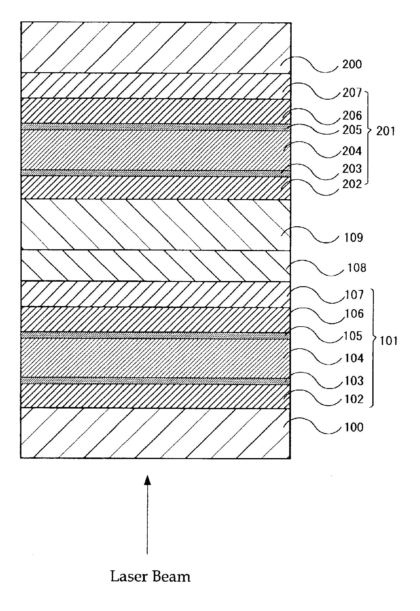
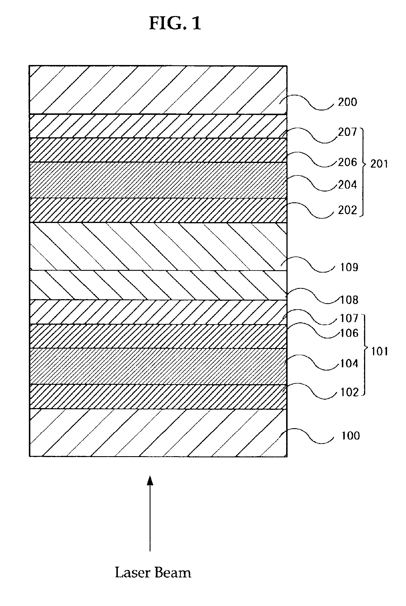
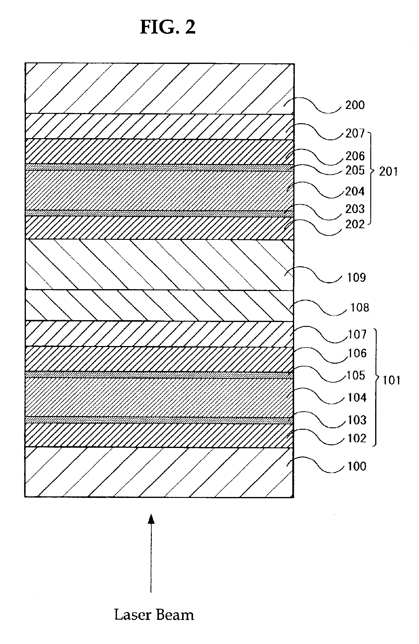
An optical recording medium having two recording layer structures which includes a cover substrate, a grooved substrate, a first recording layer structure, an intermediate layer, a separation layer, and a second recording layer structure. In the optical recording medium, the two recording layer structures include a first recording layer structure, and a second recording layer structure between the substrates, the first recording layer structure includes, in this order, a first protective layer, a first recording layer, a second protective layer, a first inorganic layer, the second recording layer structure includes, in this order, a third protective layer, a second recording layer, a forth protective layer, a second inorganic layer, and a ratio of a thickness of the first recording layer structure and a thickness of the intermediate layer is 0.2 to 1.0.

Description

BACKGROUND OF THE INVENTION[0001]1. Field of the Invention[0002]The present invention relates to optical recording medium in which information is recordable, reproduceable and rewritable at a high density and a high speed, using a laser beam irradiator.[0003]2. Description of the Related Art[0004]In an optical recording medium, a laser beam is irradiated locally to a recording material and then a difference in optical property generated thereby is used as a recording state. Use of a material having reversible change in this optical property enables rewriting the information which has been recorded. Generally, as a rewritable optical recording medium, a magneto-optical recording medium and a phase change optical recording medium are well known. These optical recording media enable recording mass of information as well as rewriting and reproducing the information at high speed simultaneously. These optical media are also excellent in portability. Accordingly, a demand has been increas...

Claims


Application Information

Patent Timeline
Patent Type & Authority Patents(United States)
IPC IPC(8): G11B7/00G11B7/0045G11B7/007G11B7/24038G11B7/24079G11B7/243G11B7/258
CPCG11B7/24038G11B7/24079G11B7/243G11B7/00454G11B2007/24316G11B2007/0013G11B2007/24308G11B2007/2431G11B2007/24314G11B7/258
Inventor SHINOTSUKA, MICHIAKISEKIYA, TAKURO
Owner RICOH KK
Learn More