
Optical switch cascading system and method with fixed incidence angle correction

a cascaded switch and incidence angle technology, applied in the field of optical signal beam manipulation and propagation, can solve the problems of difficult or impractical traditional control of signals, signal offers the potential for manipulating and conveying significant amounts of information very quickly, and most optical systems have significant potential bandwidth capacity, so as to facilitate efficient optical signal beam switching, facilitate minimization of cumulative detrimental effects, and facilitate the effect of shortening the fabric length of the cascaded switch

Inactive Publication Date: 2006-03-14
RPX CORP
View PDF24 Cites 2 Cited by
  • Summary
  • Abstract
  • Description
  • Claims
  • Application Information

AI Technical Summary

Benefits of technology

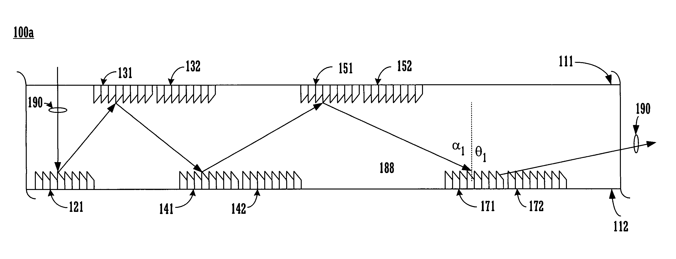
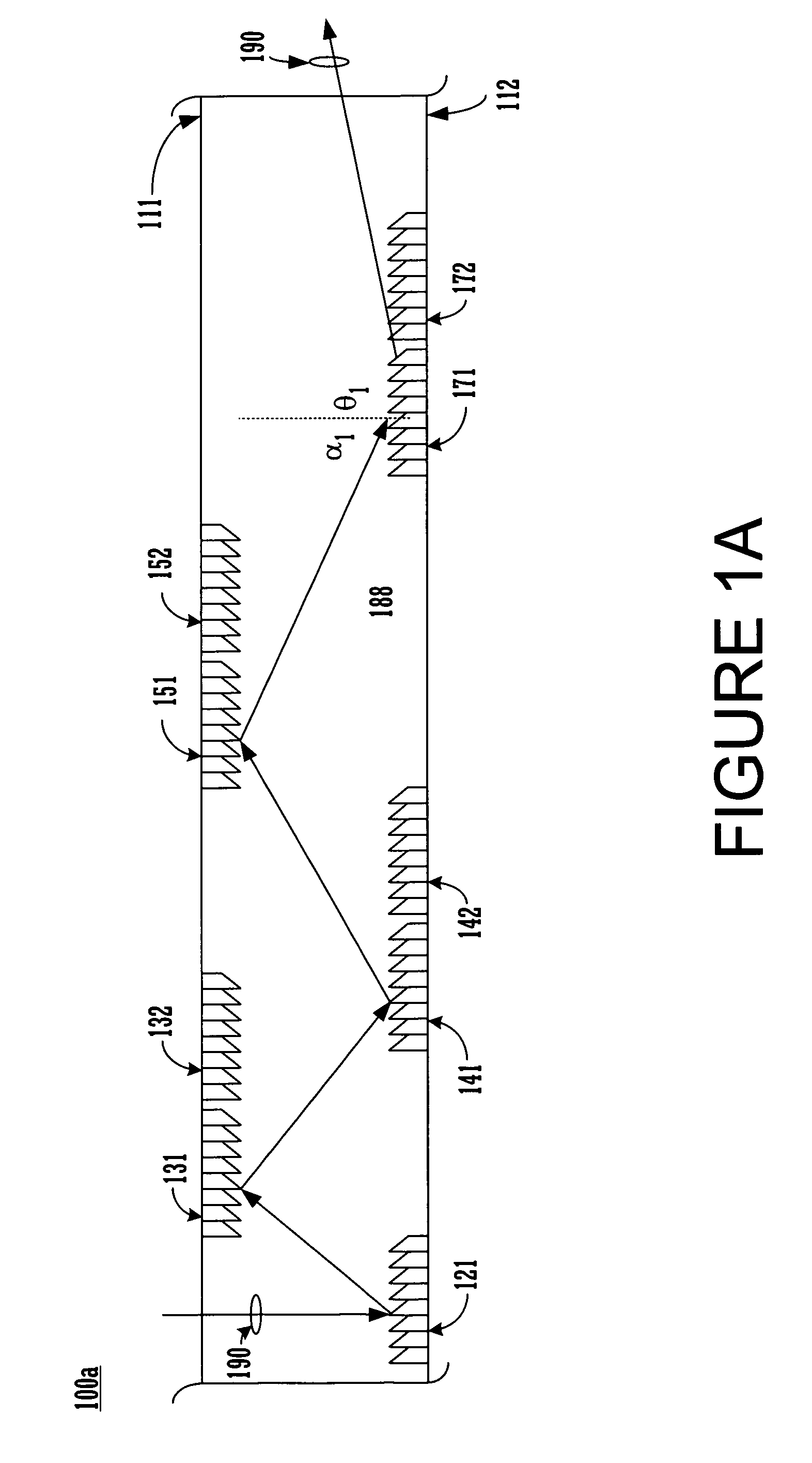
[0006]The present invention is a system and method that facilitates efficient optical signal beam switching. In one embodiment, a present invention cascaded optical switching system is included in a single integrated solution. In one exemplary implementation, the optical signal beam is directed through “free-space” (e.g., air or glass not confined by a waveguide) by cascaded switching elements. The present invention cascaded optical switching system and method facilitates minimization of cumulative detrimental impacts associated with cascaded switching of optical signal beam. For example, a present invention cascaded optical switching system can “regenerate” an optical signal beam path with a realigned or corrected incidence angle. In one embodiment of the present invention, the corrected incidence angle facilitates shortening the cascaded switch fabric length. In one exemplary implementation, a present invention cascaded optical switching system refocuses optical signal beams mitigating adverse impacts (e.g., energy loss) associated with diverging or spreading beams.
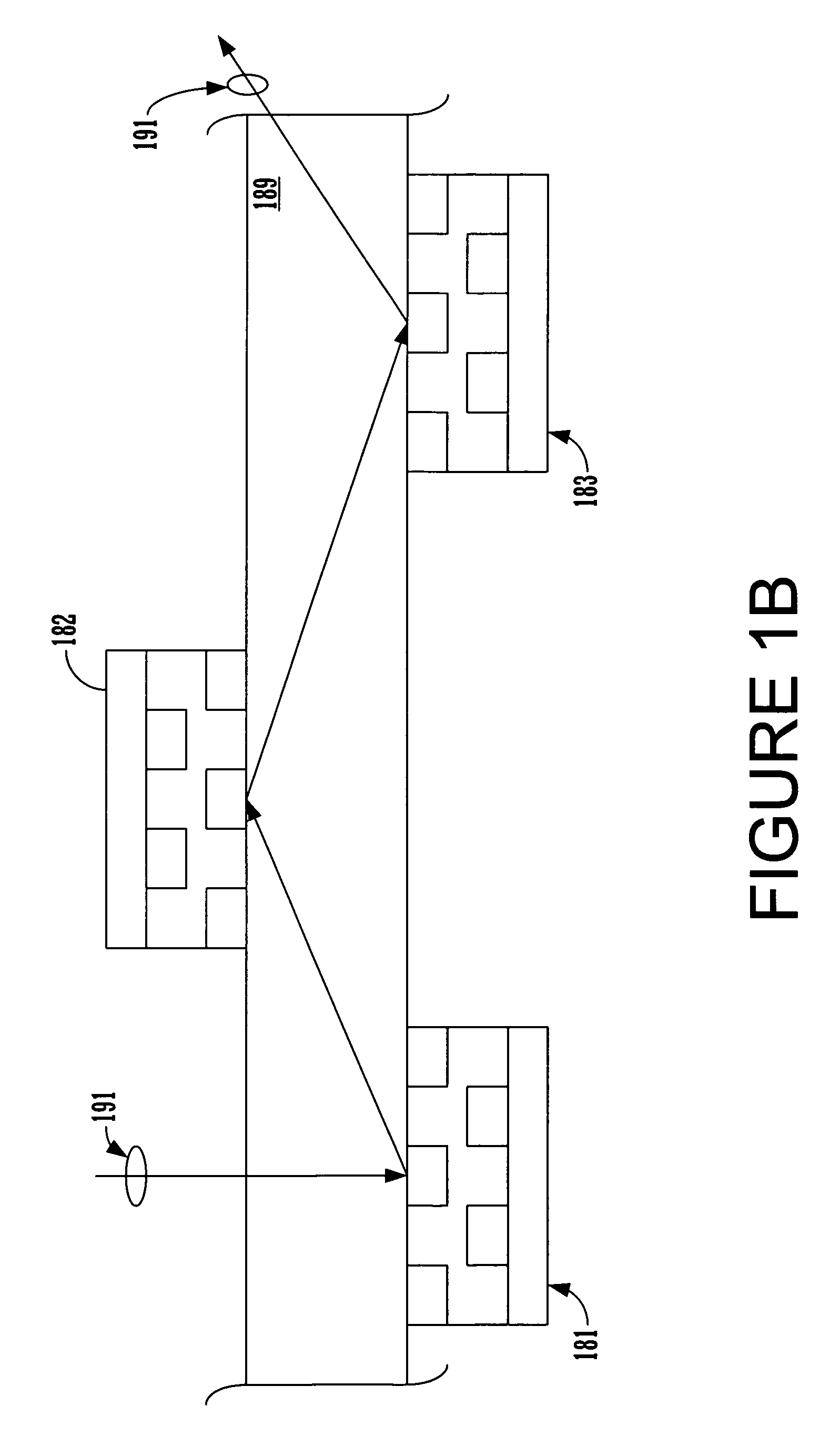
[0007]In one embodiment a cascaded optical switch fabric includes a plurality of cascaded optical switches, an optical switch support member and a bracing member. The plurality of cascaded optical switches form an optical switch fabric and direct an optical signal beam from one of the plurality of optical switches to another of the plurality of optical switches. The optical switch support member supports the plurality of cascaded optical switches in a cascaded configuration. The bracing member holds the optical switch support members in a cascading position relative to one another forming an optical switch fabric. In one embodiment of the present invention, an incidence corrective device is included in a cascaded optical switch fabric. The incidence corrective device comprises a variety of configurations including a fixed reflective component oriented at a particular angle. A corrected incidence angle permits an optical signal beam to be forwarded at a relatively shallow output angle to an optical switch located in a relatively close proximity on the cascading optical switch fabric. In one embodiment of the present invention, a cascaded optical switch fabric includes an optical signal beam spread mitigation device. In one exemplary implementation, a present invention optical signal beam spread correction device corrects beam spreading by refocusing the optical signal beam.

Problems solved by technology

However, a number of optical signal beam manipulation problems associated with achieving optimal incidence angles and / or minimal optical signal beam spreading often make traditional control of the signals difficult or impractical.
Encoding information in optical signals offers the potential for manipulation and conveyance of significant amounts of information very quickly.
For example, most optical systems have significant potential bandwidth capacity for processing and communicating a large quantity of data per unit of time.
While some types of optical signal beam controls are relatively simple and easy to accomplish such as transmission of an optical signal beam along a confined single waveguide path (e.g., formed by a fiber optic cable strand), other types of optical signal beam control such as dynamically directing an optical signal beam along various paths are relatively difficult.
These traditional attempts typically consume significant resources to manufacture each discrete switch of limited capability and additional resources to “wire” them together (e.g., connect cables between each individual limited switch).
These approaches are usually slow and require significant resources to implement.
Switching optical signal beams typically involves significant challenges for single switches capable of directing optical signal beams along a variety of paths.
The nature of light propagation gives rise to a number of complications that can potentially limit or impede the ability to direct an optical signal beam to a particular destination.
Cumulative detrimental effects associated with repeated redirection of optical signals tend to limit the practical utilization of traditional optical switches for applications involving significant control flexibility.
The relationship of incidence angles and output angles can give rise to detrimental effects in situations where angles become cumulatively deeper each time an optical switch redirects an optical signal beam.
Large incidence angles often prevent the propagation of an optical signal beam to a nearby device at an optimal incidence angle.
Another potential detrimental impact of repeated redirection of an optical signal beam is deteriorating divergence or spread of the optical signal beam.
Each time an optical beam is switched it spreads and a portion of the signal energy is lost.
Theses energy losses are typically cumulative and have adverse impacts on interpreting the weakened signals.

Method used


Image

  • Optical switch cascading system and method with fixed incidence angle correction
  • Optical switch cascading system and method with fixed incidence angle correction
  • Optical switch cascading system and method with fixed incidence angle correction

Examples


Embodiment Construction

[0029]Reference will now be made in detail to the preferred embodiments of the invention, an optical switch cascading system and method with fixed incidence angle correction, examples of which are illustrated in the accompanying drawings. While the invention will be described in conjunction with the preferred embodiments, it will be understood that they are not intended to limit the invention to these embodiments. On the contrary, the invention is intended to cover alternatives, modifications and equivalents, which may be included within the spirit and scope of the invention as defined by the appended claims. Furthermore, in the following detailed description of the present invention, numerous specific details are set forth in order to provide a thorough understanding of the present invention. However, it will be obvious to one ordinarily skilled in the art that the present invention may be practiced without these specific details. In other instances, well known methods, procedures,...


PUM


Abstract

The present invention is an efficient system and method for cascading optical switches. A plurality of cascaded optical switches form a cascaded optical switch fabric and direct an optical signal beam from one of the plurality of optical switches to another of the plurality of optical switches. In one embodiment of the present invention, a fixed incidence corrective device is included in a cascaded optical switch fabric. The incidence corrective device directs an optical signal beam in a shallow angle so that it strikes the next optical switch at a corrected incidence angle. A corrected incidence angle permits an optical signal beam to be forwarded at a relatively shallow angle to an optical switch located in a relatively close proximity on the optical switch fabric. The present invention also provides for refocusing of spreading optical signal beams and mitigation of signal loss.

Description

FIELD OF THE INVENTION[0001]The present invention relates to the field of optical signal beam manipulation and propagation. More particularly, the present invention relates to a system and method to facilitate cascaded switching of optical signal beams with incidence angle correction and beam spread correction.BACKGROUND OF THE INVENTION[0002]Systems utilizing various types of signals to represent information have made a significant contribution towards the advancement of modern society and are utilized in a number of applications to achieve advantageous results. Numerous technologies such as digital computers, calculators, audio devices, video equipment, and telephone systems facilitate increased productivity and cost reduction in analyzing and communicating information in most areas of business, science, education and entertainment. Advanced optical signal based technologies offer the potential for rapid processing and communication of large amounts of data associated with a varie...

Claims


Application Information

Patent Timeline
Patent Type & Authority Patents(United States)
IPC IPC(8): G02B6/34G02B6/35
CPCG02B26/0816G02B26/0808G02B6/43
Inventor MAHESHWARI, DINESH
Owner RPX CORP
Learn More