Implantable medical device communication system

a communication system and medical device technology, applied in the field of interfaces for communication, can solve the problems of limited power and memory, limited space for additional circuitry, and large amount of available power, and achieve the effect of improving data communication rate and reducing command length

Inactive Publication Date: 2006-03-14
MEDTRONIC INC
View PDF216 Cites 223 Cited by
  • Summary
  • Abstract
  • Description
  • Claims
  • Application Information

AI Technical Summary

Benefits of technology

[0005]The present implantable medical device communication system includes an implantable medical device (“IMD”) running a master clock. Slave devices resynchronize to the IMD clock on the rising edge. The sensor interface improves the data communication rate and permits simultaneous or individual communication with a plurality of external sensors. A 2-wire bus provides power, clock, and data from a single master to up to 16 slave devices. Half-duplex communication and pulse width modulation of the voltage on the bus allow a raw data rate of approximately 100 Kbps. The data is encoded as “1's” and “0's” for data transmission between the master and slave devices. An initialization procedure determines the long address of each slave device and assigns a short address to reduce command length.

Problems solved by technology

At the same time, the implantable medical device operates by way of an internal power source, usually in the form of a battery, which has a limited amount of available power.
Since the sensors are often required to be placed within the heart, the amount of available space for additional circuitry, power and memory is limited.

Method used


Image

  • Implantable medical device communication system
  • Implantable medical device communication system
  • Implantable medical device communication system

Examples


Embodiment Construction

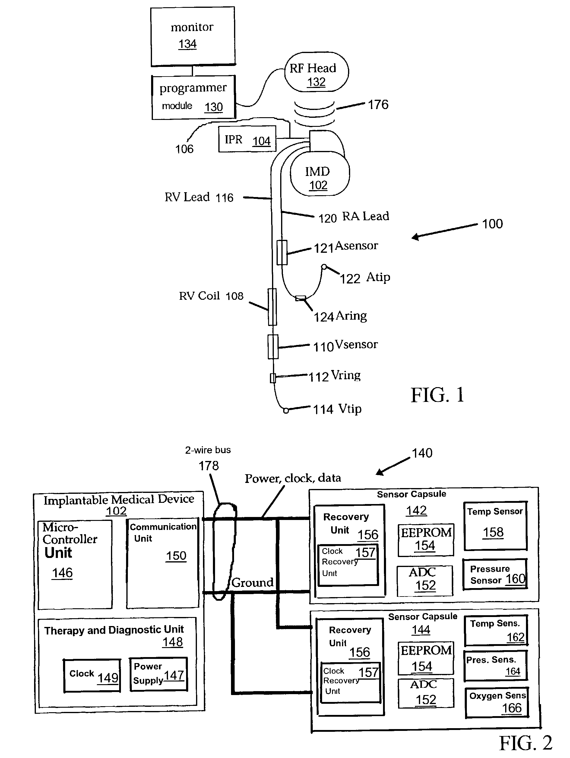
[0065]With reference now to the drawings, wherein like numbers refer to like elements throughout, embodiments of the invention are now described. FIG. 1 is a schematic diagram of an implantable medical device system 100 according to an embodiment of the invention. As illustrated, implantable medical device (“IMD”) 102 takes the form of an internal cardio defibrillator or pacemaker, for example, with implantable pressure reference, right ventricular (“RV”) pressure, and RV oxygen. System 100 includes IMD 102 that communicates with internal pressure reference (“IPR”) 104 communication bus 106.

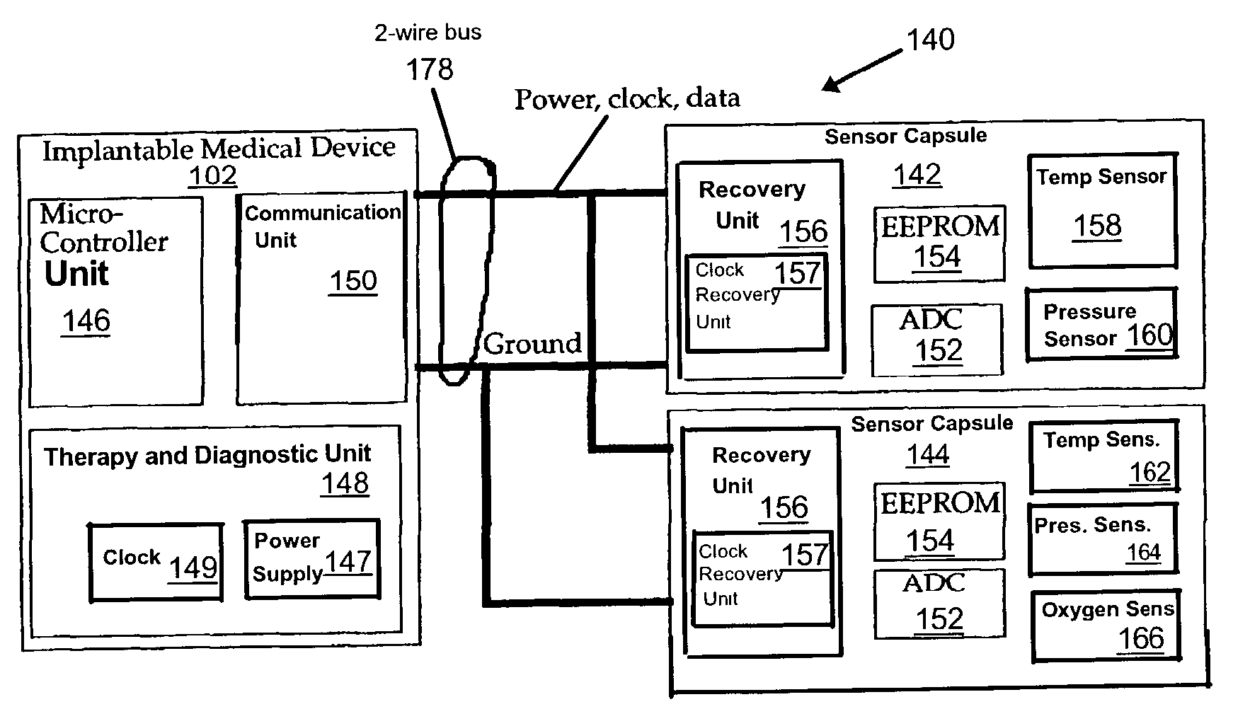
[0066]IMD 102 is electrically connected with right ventricular coil (“RV coil”) 108, Vsensor 110, Vring 112, and Vtip 114 by way of right ventricular lead (“RV lead”) 116. The RV lead 116 has a true bipolar lead (Vtip 114, Vring 112) for differential sensing, along with a Vsensor capsule 110, and RV Coil 108 for high voltage defibrillation therapy. The Vsensor capsule 110 contains a pressure sens...


PUM


Abstract

An implantable medical device communication system communicates information between an implantable medical device and at least one slave device by way of a two-wire bus. Slave devices may include remote sensors and other implantable medical devices. The implantable medical device includes a communication unit to combine data and power for transmission over the two wire bus. The transmitted signal is selectively changeable between a first and second voltage. The slave device includes a recovery unit to recover data and power from the received signal. An extendable command set includes long commands to set up the system and shorter commands to conserve power. Selectively addressable multicast commands, and shortened quick trigger commands conserve power by lowering system current and increasing data throughput.

Description

FIELD OF THE INVENTION[0001]The present invention relates to an interface for communication between primary and secondary devices along a two-wire communication bus. More particularly, the present invention relates to an interface for bi-directional communication between an implantable medical device and a plurality of slave devices such as sensors along a two-wire communication bus.BACKGROUND OF THE INVENTION[0002]Implantable medical devices take many forms to provide therapy to a patient. For example, implantable medical devices provide pacing therapy to assist in maintaining proper heart rhythm. Pacing therapy may be applied to treat a number of conditions, such as atrial fibrillation, atrial tachyarrhythmia, atrial arrhythmias, ventricular fibrillation, ventricular tachyarrhythmia, and bradyarrhythmias caused by heart block or sinus node dysfunction. Implantable medical devices may also take the form of an implantable cardioverter defibrillator to provide therapy for sudden card...

Claims


Application Information

Patent Timeline
Patent Type & Authority Patents(United States)
IPC IPC(8): A61N1/37A61B5/04A61N1/372
CPCA61N1/372A61N1/025
Inventor REINKE, JAMES D.ECKER, ROBERT M.
Owner MEDTRONIC INC
Why Eureka
Try Eureka