
Machine tool and pallet changer for machine tool

a machine tool and pallet changer technology, applied in the field of pallet changers, can solve the problems of complicated pallet changers, prolonged time for changing pallets, and enlarged overall apparatus, and achieve the effect of simple and compact structure, short time-consuming change of pallets

Inactive Publication Date: 2006-03-21
MORI SEIKI HITECH
View PDF9 Cites 50 Cited by
  • Summary
  • Abstract
  • Description
  • Claims
  • Application Information

AI Technical Summary

Benefits of technology

[0007]In order to overcome the above-noted defects, an object of the present invention is to provide a pallet changer, which becomes simple and compact and may change the pallets in a short period of time, and a machine tool provided with the pallet changer.
[0017]With such a structure of the pallet changer according to the present invention, it is possible to change the pallets in a short period of time and the structure of the pallet changer becomes simple and compact.

Problems solved by technology

Accordingly, the time for changing the pallets is likely to be prolonged, and also, there is a tendency that the pallet changer becomes complicated and the overall apparatus would be enlarged.

Method used


Image

  • Machine tool and pallet changer for machine tool
  • Machine tool and pallet changer for machine tool
  • Machine tool and pallet changer for machine tool

Examples


Embodiment Construction

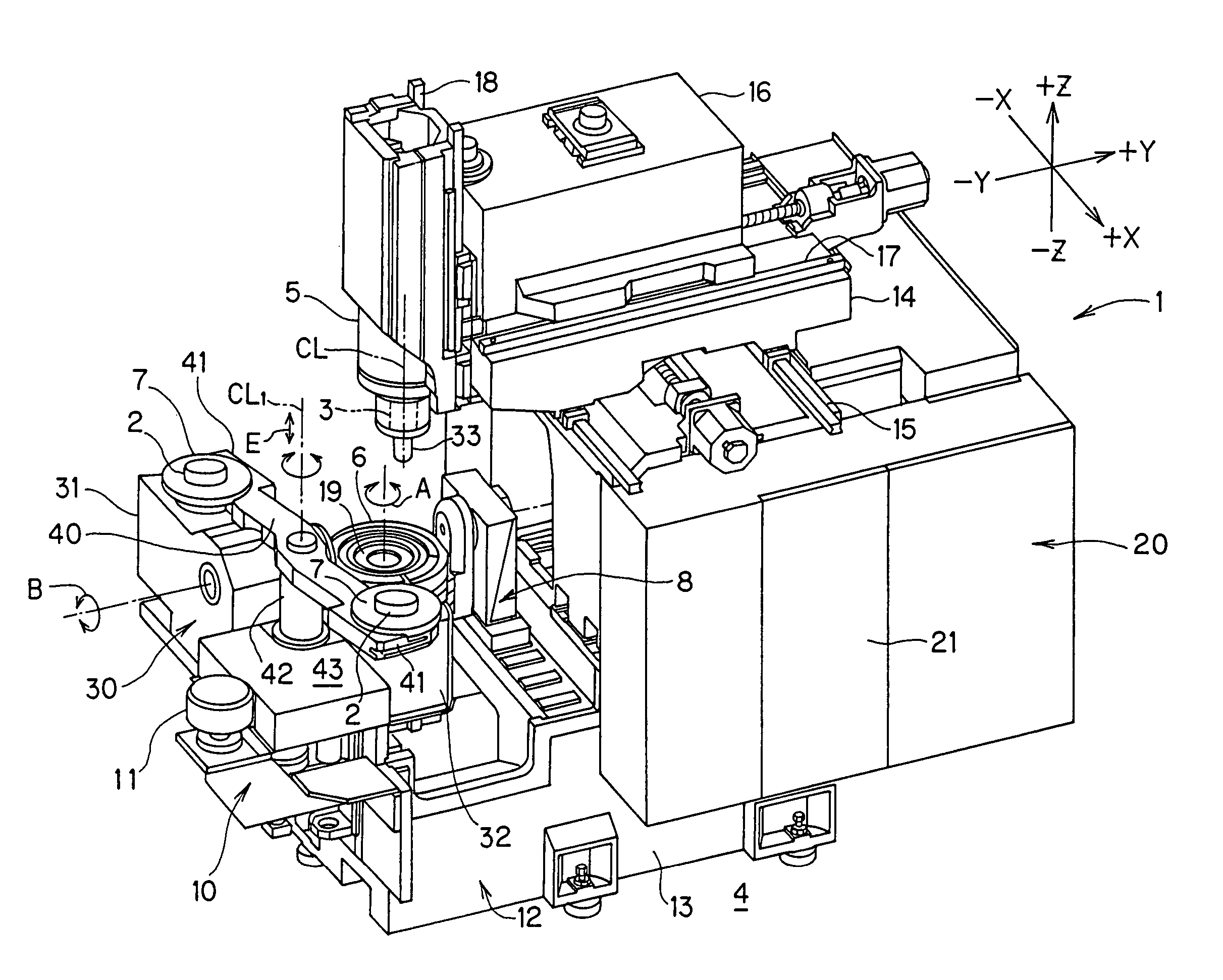
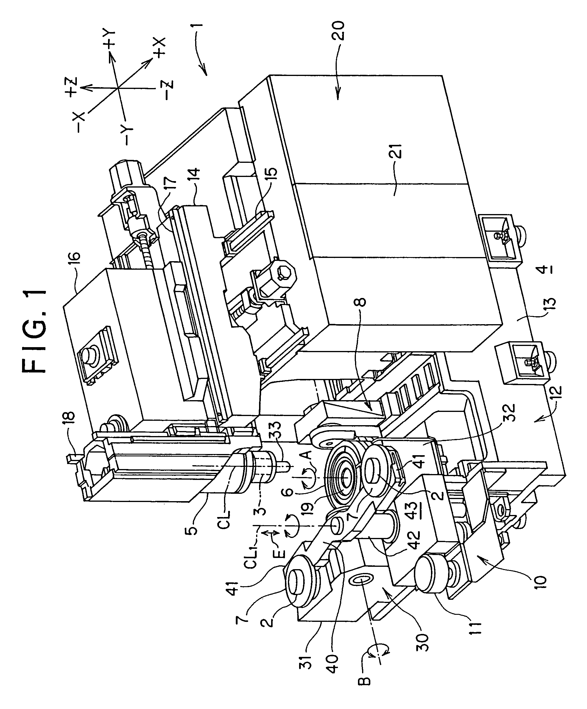
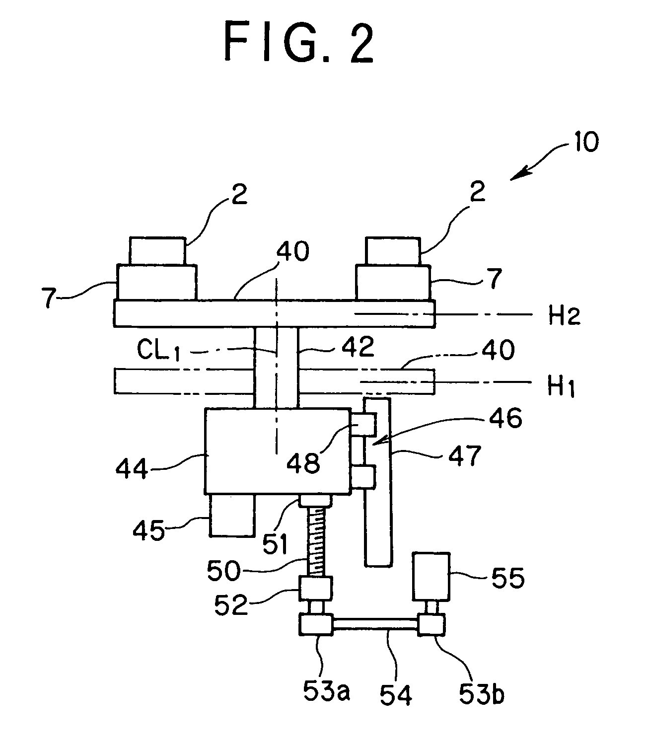
[0021]An embodiment of the present invention will now be described with reference to the accompanying drawings FIGS. 1 to 3J.

[0022]FIG. 1 is a perspective view of a vertical machining center. FIG. 2 is a schematic structural view of the operation of an automatic pallet changer provided in the vertical machining center. FIGS. 3A to 3J are illustrations of the operation of the automatic pallet changer.

[0023]FIGS. 1 to 3J show the vertical machining center (hereinafter referred to as MC) 1 as a machine tool according to this embodiment. This MC 1 is the machine tool which may machine a workpiece 2 in a five-axis control.

[0024]The MC 1 is controlled by a controller 20 which is composed of an NC (numerical control) unit and a programmable logic controller (PLC). Incidentally, the controller 20 may be a controller in which the PLC portion is built in the NC unit.

[0025]An axis CL of a main spindle 3 of the MC 1 is directed in the vertical direction to a floor surface 4. Incidentally, the a...


PUM

PropertyMeasurementUnit
Angleaaaaaaaaaa

Abstract

An APC is provided in a five-axis controlling vertical machining center. A spindle head is movable in three mutually transverse axes directions to a workpiece. A table disposed below swings to be positioned and is directed upwardly and indexed. A pallet setup base is provided outside a machining area. A pallet change arm has pallet grip portions for gripping and releasing the pallets. The arm makes a swivel motion and makes an ascending and descending motion. Thus, the pallet is transferred between the table and the pallet setup base and is received and discharged to the table and the pallet setup base.

Description

BACKGROUND OF THE INVENTION[0001]1. Field of the Invention[0002]The present invention relates to a pallet changer for changing pallets, on which workpieces are placed, and feeding the workpiece to a table of a machine tool and also relates to the machine tool provided with the pallet changer.[0003]2. Description of the Related Art[0004]For example, Japanese Utility Model Application Laid-Open No. 7-3938 discloses a pallet changer for a machine tool. The pallet changer may automatically discharge a pallet mounted on the table in the machine tool such as a machining center and may automatically feed a next pallet onto the table.[0005]The pallet changer is provided with a base disposed in the vicinity of the table, a reciprocating base which may be moved to-and-fro on the base, a swivel shaft arranged, to be able to swivel about a vertical axis, on the reciprocating base and a swivel arm. The swivel arm has a size, such that two pallets may be placed thereon, and is supported by the sw...

Claims


Application Information

Patent Timeline
IPC IPC(8): B23Q41/00B23Q7/00B23Q7/14
CPCB23Q7/1431Y10T29/5124Y10T409/308792Y10T29/5196Y10T82/2514Y10T29/5114Y10T82/2511
Inventor YASUDA, HIROSHIISHIDA, TOMOAKI
Owner MORI SEIKI HITECH
Learn More