Battery cooling system for vehicle

a battery cooling and vehicle technology, applied in the field of battery cooling systems, can solve the problems of restricting the temperature inside the passenger compartment from being increased, the cooling capacity of the passenger compartment by the air conditioner is not reduced, etc., and achieves the effect of reducing the compression capacity of the compression device, reducing the cooling capacity of the passenger compartment, and accurately controlling the operation of the compressor

Active Publication Date: 2006-03-21
DENSO CORP
View PDF13 Cites 37 Cited by
  • Summary
  • Abstract
  • Description
  • Claims
  • Application Information

AI Technical Summary

Benefits of technology

[0008]In view of the above-described problems, it is an object of the present invention to provide a battery cooling system for a vehicle, which can stably control an inside air temperature of a passenger compartment and operation of a compressor.
[0009]It is another object of the present invention to provide a vehicle apparatus including an air conditioner and a battery cooling system, in which an inside air temperature of the passenger compartment and operation of a compressor can be stably controlled while cooling capacity of the air conditioner and cooling capacity of a battery can be improved.
[0010]According to the present invention, a battery cooling system cools a battery mounted on a vehicle by using conditioned air of an air conditioner. The air conditioner includes a compression device having a variable compression capacity for compressing refrigerant, an air conditioning case for defining an air passage through which air flows into a passenger compartment of the vehicle through an air outlet portion, a cooling heat exchanger for cooling air by using refrigerant from the compression device, and an air-conditioning control unit which controls a cooling capacity of the cooling heat exchanger by controlling a compression capacity of the compression device. The battery cooling system includes a battery case for accommodating the battery and having an air supply passage through which air inside the passenger compartment is introduced to be supplied to the battery, a blower disposed in the battery case for blowing air introduced into the air supply passage to the battery, and a battery control unit which controls the blower to increase an air amount supplied to the battery when a predetermined condition is satisfied. Further, the air-conditioning control unit decreases the compression capacity of the compression device after the air amount supplied to the air supply passage of the battery case from the passenger compartment is increased to a predetermined amount. Accordingly, it can restrict the temperature inside the passenger compartment from being rapidly increased again when the air amount supplied to the air supply passage of the battery case from the passenger compartment is increased.
[0011]Preferably, the air-conditioning control unit decreases the compression capacity of the compression device after a predetermined time passes after the air amount supplied to the air supply passage of the battery case is increased to the predetermined amount. In this case, even when the air amount blown to the battery is increased, because the compression capacity of the compression device is not reduced for the predetermined time, the cooling capacity of the passenger compartment by the air conditioner is not reduced due to the increased air blowing amount to the battery. As a result, it can restrict the temperature inside the passenger compartment from being increased again, immediately after a cool-down operation of the air conditioner. Therefore, the temperature inside the passenger compartment and the operation of the compressor can be stably controlled.
[0013]Alternatively, the predetermined condition is satisfied when a target temperature calculated by a target temperature calculation means is higher than a first predetermined temperature. In this case, the air-conditioning control unit decreases the compression capacity of the compression device when the calculated target temperature is higher than a second predetermined temperature that is higher than the first predetermined temperature. Therefore, the temperature inside the passenger compartment and the operation of the compressor can be accurately controlled. In contrast, the battery control unit controls the blower to decrease the air amount supplied to the battery when the calculated target temperature is lower than the first predetermined temperature.
[0014]The present invention can be suitably applied to a vehicle apparatus with the air conditioner and the battery cooling system. In this case, cooling capacity of the passenger compartment and cooling capacity of the battery can be improved while the temperature inside the passenger compartment and the operation of the compressor can be stably controlled.

Problems solved by technology

In this case, even when the air amount blown to the battery is increased, because the compression capacity of the compression device is not reduced for the predetermined time, the cooling capacity of the passenger compartment by the air conditioner is not reduced due to the increased air blowing amount to the battery.
As a result, it can restrict the temperature inside the passenger compartment from being increased again, immediately after a cool-down operation of the air conditioner.

Method used


Image

  • Battery cooling system for vehicle
  • Battery cooling system for vehicle
  • Battery cooling system for vehicle

Examples


first embodiment

(First Embodiment)

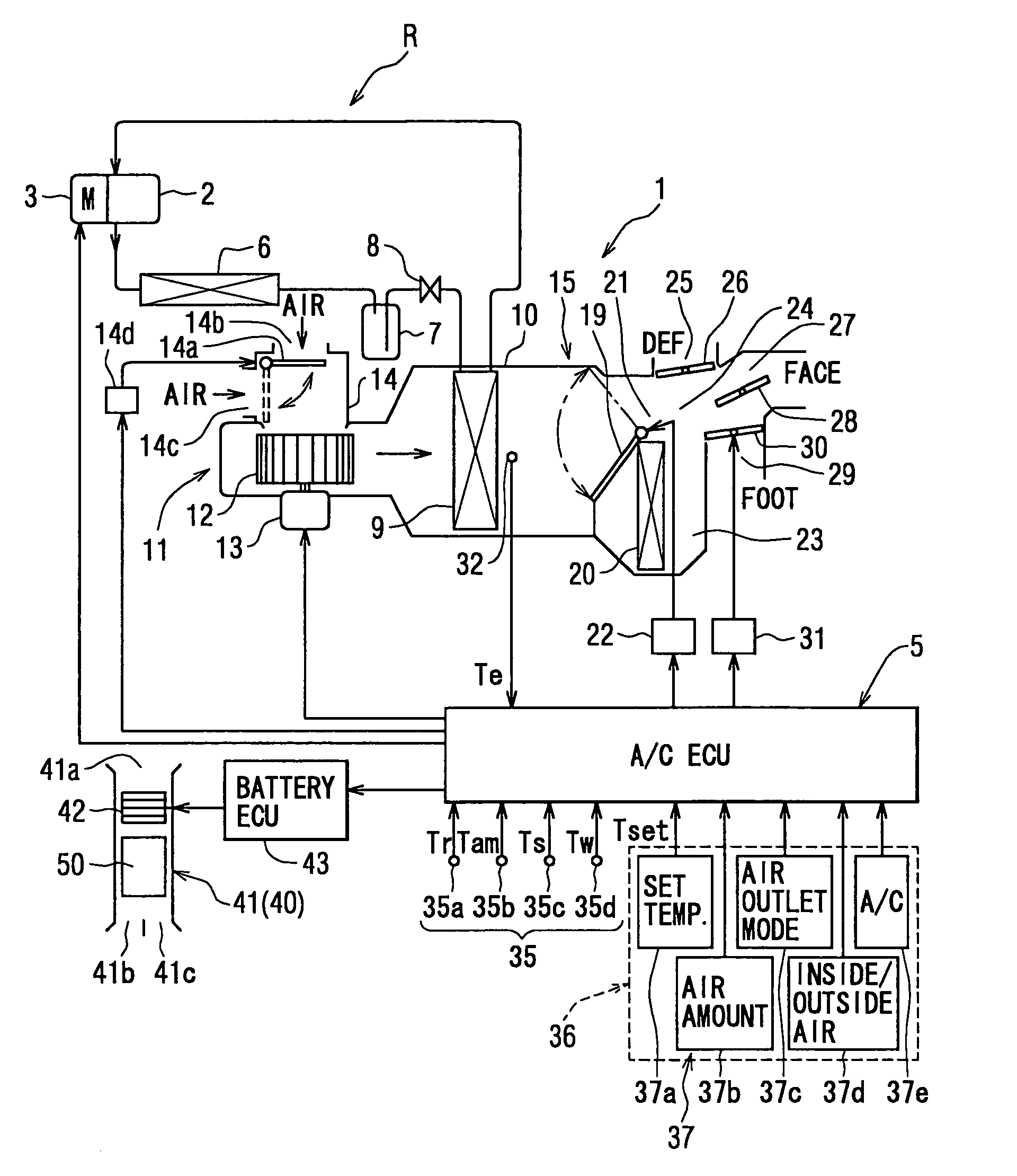
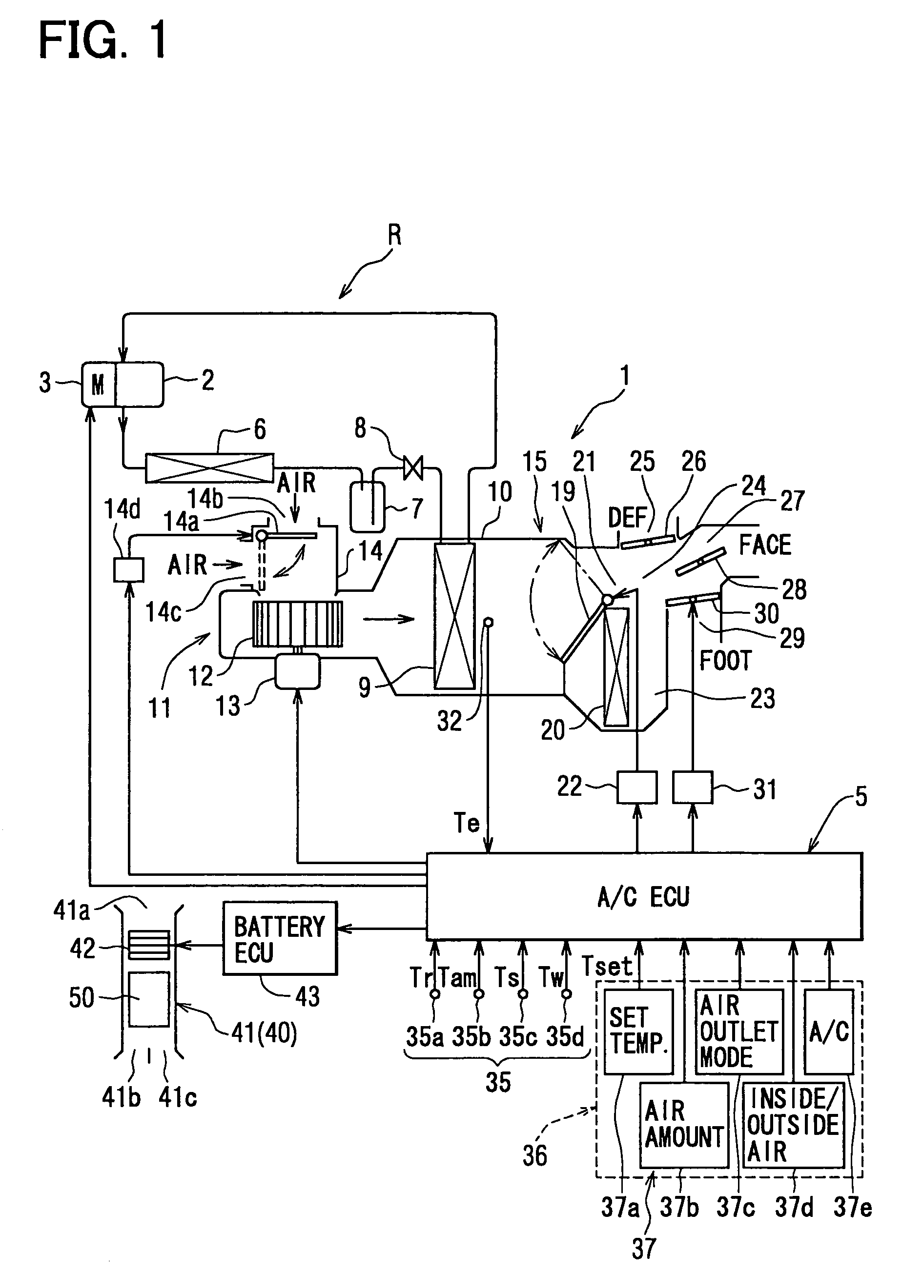
[0032]The first embodiment of the present invention will be now described with-reference to FIGS. 1–11. As shown in FIG. 1, a vehicle air conditioner 1 includes a refrigerant cycle R that is provided with an electrical compressor 2 for sucking and compressing refrigerant and for discharging the compressed refrigerant. The electrical compressor 2 is integrated with an electrical motor 3 to be operated by electrical power of the electrical motor 3. Therefore, a rotation speed (compression capacity) of the electrical compressor 2 is changed by changing the rotation speed of the electrical motor 3. The rotation speed of the electrical motor 3 is controlled by an air conditioning ECU 5 so as to control the compression capacity (cooling capacity) of the electrical compressor 2.

[0033]High-temperature and high-pressure gas refrigerant discharged from the electrical compressor 2 flows into a condenser 6 (high-pressure heat exchanger, refrigerant radiator), and is heat-excha...

second embodiment

(Second Embodiment)

[0068]The second embodiment of the present invention will be now described with reference to FIG. 12. In the above-described first embodiment, the inside air temperature Tr is compared with the first predetermined inside air temperature at step S23, and the upper limit rotation speed IVOmax is decreased to the second predetermined value. IVO2 at step S25b after the predetermined time t1 passes after the air amount to be blown to the battery 50 is increased. However, in the second embodiment, at step S231 in FIG. 12, it is determined whether or not the inside air temperature Tr is larger than a second predetermined inside air temperature Tr2 that is lower than the first predetermined inside air temperature Tr1. Further, at step S25 in FIG. 12, when the target air temperature TAO is equal to or higher than the first predetermined target temperature TAO1 or when the inside air temperature Tr is equal to or lower than the second predetermined inside air temperature Tr...

third embodiment

(Third Embodiment)

[0072]The third embodiment of the present invention will be now described with reference to FIG. 13. In the third embodiment, step S231 of the second embodiment shown in FIG. 12 is changed to step S232 in FIG. 13. In the third embodiment, the other parts are the same as that described in the second embodiment.

[0073]In the third embodiment, at step S232, when the inside air temperature Tr is reduced by a predetermined temperature ΔT from the first predetermined inside air temperature Tr1 at step S232, the upper limit rotation speed of the compressor 2 is reduced at step S25 so that the cooling capacity of the compressor 2 is reduced.

[0074]According to the third embodiment, even when the inside air temperature Tr is equal to or lower than the first predetermined inside air temperature Tr1, the upper limit rotation speed is not reduced to the second predetermined valve IVO2. When the inside air temperature Tr is further reduced by the predetermined temperature ΔTr fro...


PUM

PropertyMeasurementUnit
temperatureaaaaaaaaaa
cooling capacityaaaaaaaaaa
temperatureaaaaaaaaaa

Abstract

In a battery cooling system that cools a battery by using conditioned air (inside air of a passenger compartment) of a vehicle air conditioner, a battery control unit controls a battery blower to increase an air amount supplied to the battery when a predetermined condition is satisfied. In contrast, an air-conditioning control unit decreases a compression capacity of a compression device after an air amount supplied to the battery is increased to a predetermined amount by the battery control unit. For example, the air-conditioning control unit decreases the compression capacity of the compression device after a predetermined time passes after the air amount supplied to the battery is increased to the predetermined amount. Accordingly, the temperature inside the passenger compartment and the compression device can be stably controlled.

Description

CROSS REFERENCE TO RELATED APPLICATION[0001]This application is based on Japanese Patent Application No. 2003-287094 filed on Aug. 5, 2003, the disclosure of which is incorporated herein by reference.FIELD OF THE INVENTION[0002]The present invention relates to a battery cooling system for cooling a battery mounted on a vehicle by using conditioned air of a vehicle air conditioner. More particularly, the present invention is suitably used for cooling a battery that is mounted as a drive source of an electrical motor in an electrical vehicle having the electrical motor for a vehicle running, or a hybrid vehicle having an engine and the electrical motor for the vehicle running.BACKGROUND OF THE INVENTION[0003]In an electrical vehicle having an electrical motor used for a vehicle running, a battery to be charged is used as a driving source of the electrical motor, and the electrical motor drives the vehicle by the electrical power supplied from the battery. In this electrical vehicle, t...

Claims


Application Information

Patent Timeline
Patent Type & Authority Patents(United States)
IPC IPC(8): F25D17/04B60W20/00F25D17/00B60H1/00B60H1/32B60K6/28B60K11/06B60W10/30H01M10/60H01M10/613H01M10/625H01M10/633H01M10/6556H01M10/6563H01M10/663
CPCB60H1/00278B60H2001/003B60L1/003B60L1/02B60L2240/34B60L2240/545B60L2240/662B60L2260/56B60L58/26H01M2220/20H01M10/613H01M10/625H01M10/63H01M10/6563H01M10/663Y02E60/10Y02T10/70Y02T10/72Y02T90/16B60L3/0046
Inventor YOSHIDA, MAKOTOOOMURA, MITSUYOHOMAN, TOSHINOBUHONDA, KEITAKISHITA, HIROSHI
Owner DENSO CORP
Why Eureka
Try Eureka