Apparatus for cooling fluids

a technology for distributing apparatuses and fluids, which is applied in the direction of domestic cooling apparatus, lighting and heating apparatus, liquid transferring devices, etc. it can solve the problems of reducing affecting the quality of beer, so as to reduce the service requirements of beer dispensing, reduce yeast activity and growth, and avoid the possibility of reheating of cooled fluids.

Inactive Publication Date: 2006-03-21
MANITOWOC FOODSERVICE CO LLC
View PDF26 Cites 28 Cited by
  • Summary
  • Abstract
  • Description
  • Claims
  • Application Information

AI Technical Summary

Benefits of technology

[0047]Another advantage of the present invention is that cooling of the fluids occurs immediately before the point at which the fluids are dispensed, rather than at an intermediate location from which the fluids must subsequently be transferred. Thus, potential reheating of cooled fluids is avoided.
[0048]The cold temperatures afforded by the present invention also help reduce yeast activity and growth, which reduces the service requirements for beer dispensing.
[0049]That is, beer lines according to the invention require less frequent cleaning due to the reduced yeast growth, typically every 3–4 weeks rather than every week as is presently the case with known beer dispensing apparatus. This represents a significant saving in cleaning expense and down time.
[0050]Other objects, features and advantages of the present invention will become apparent to those skilled in the art from the following detailed description. It is to be understood, however, that the detailed description and specific examples, while indicating preferred embodiments of the present invention, are given by way of illustration and not limitation. Many changes and modifications within the scope of the present invention may be made without departing from the spirit thereof, and the invention includes all such modifications.

Problems solved by technology

If beer is not properly handled, in excess of 50% of the beer can be lost to waste, in the form of foam.
Thus, beer in a glass containing a large volume of foam is likely to have lost so much gas that it is flat and of inferior character, if not unmerchantable.
The gas in beer is quite unstable and is such that if let or caused to rapidly expand, as result of rapid thermal heating of the beer or as a result of a rapid reduction of pressure on the beer, it will immediately reach or attain a highly excited state in which adjacent expanding bubbles of beer displace the liquor of the beer and continue to establish ever-increasing larger bubbles of gas that cannot be contained by and that seek to escape or separate from the beer.
While the noted balance lines are effective to eliminate or greatly reduce those adverse effects that result from a rapid release of pressure on beer, they have little or no effect in preventing the adverse effects that result from progressive warming of the beer and expansion of the gas contained therein.
As a result of the foregoing, while the provision and use of the above-noted balance lines attains beneficial end results, they are not wholly effective to prevent the escape of gas from beer flowing therethrough and the generating of excess foam that is discharged through and from the tap heads with the beer that is dispensed.
This represents a significant loss of product.
While the above-noted glycol systems would appear to establish good and effective heat exchanger means that would work to prevent warming of beer flowing through the beer lines and balance lines, they do not prevent warming of the beer but simply slow the rate at which the beer warms as it flows from the kegs to the tap heads.
This is due to the fact that the plastic tubing of which the several lines are established has an extremely low coefficient of heat conductivity.
Further, due to space limitations and the like, the thermal-insulating jackets used in trunk lines are not so efficient a barrier of heat to prevent more heat from entering the trunk lines and reaching the beer delivery lines than can be carried away by the glycol flowing through the glycol lines.
That warming of the beer that does take place and results in expansion of the gas entrained in that beer to render the gas highly unstable and very likely to commence to separate from the beer.
This further destabilizes the gas in the beer and renders it such that when the tap heads are opened, and the pressure on the beer is released, gas commences to escape from the beer, generating foam which is dispensed from the tap heads together with that beer which is not foamed.
Those heat exchangers have proven to be notably less efficient and effective than the above-noted cold plate type heat exchangers.
While this form of heat exchange means is effective to chill beer that is let to stand in the balance lines, the glycol is incapable of carrying off heat from the beer (through the walls of the balance lines) at a sufficient rate to notably chill beer that is continuously flowing through the balance lines at a rate of, for example, 4 ounces per second.
As a result of the foregoing, when beer is dispensed from systems including the last-noted form of heat exchanger means, the beer dispensed is seldom uniform, that is, it intermittently runs clear and free of foam and then runs laded with foam for short periods of time.
Additional problems arise in situations in which very large quantities of beverages must be dispensed, and in situations in which it is impossible or impractical to store beverages in volume, such as kegs of beer, in a low-temperature environment prior to dispensing the beverage.

Method used


Image

  • Apparatus for cooling fluids
  • Apparatus for cooling fluids
  • Apparatus for cooling fluids

Examples


Embodiment Construction

[0036]In accordance with one aspect of the present invention, there is provided a cold plate unit that includes a coolant system, a fluid system and a metallic unit.

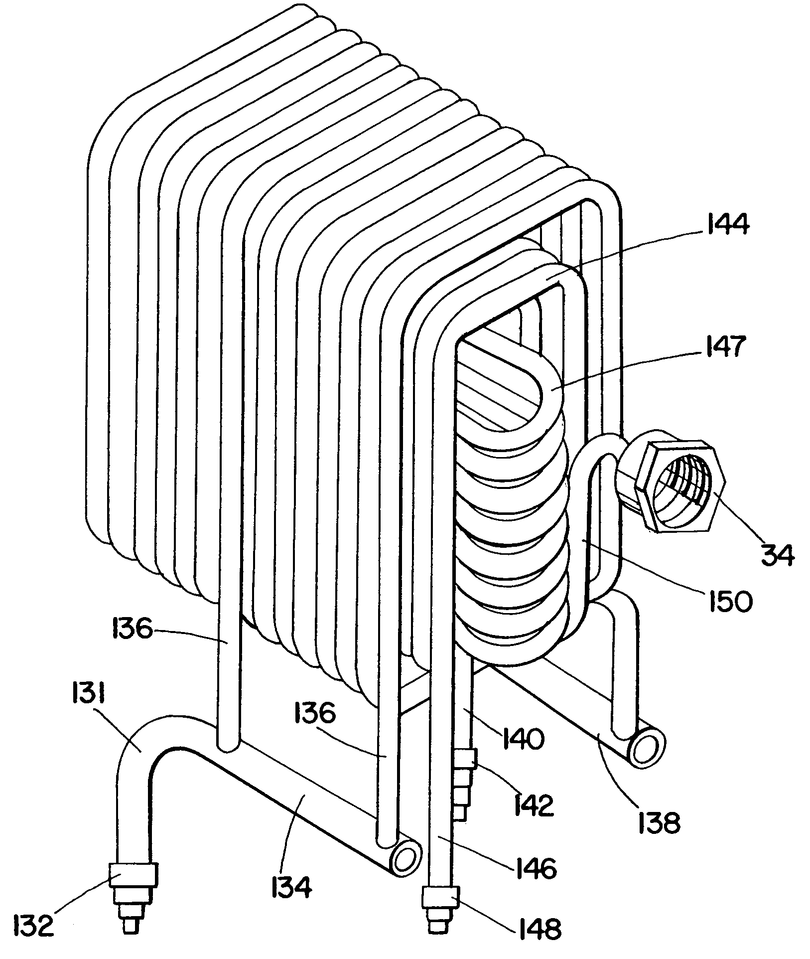
[0037]The coolant system includes a primary inlet manifold, a secondary inlet manifold, a secondary outlet manifold and a primary outlet manifold, and further includes a first plurality of coolant line segments connecting the primary inlet manifold and the secondary inlet manifold and a second plurality of coolant line segments connecting the secondary outlet manifold and the primary outlet manifold. The fluid system is in heat exchange relationship with the coolant system. The metallic unit incorporates the coolant system and the fluid system.

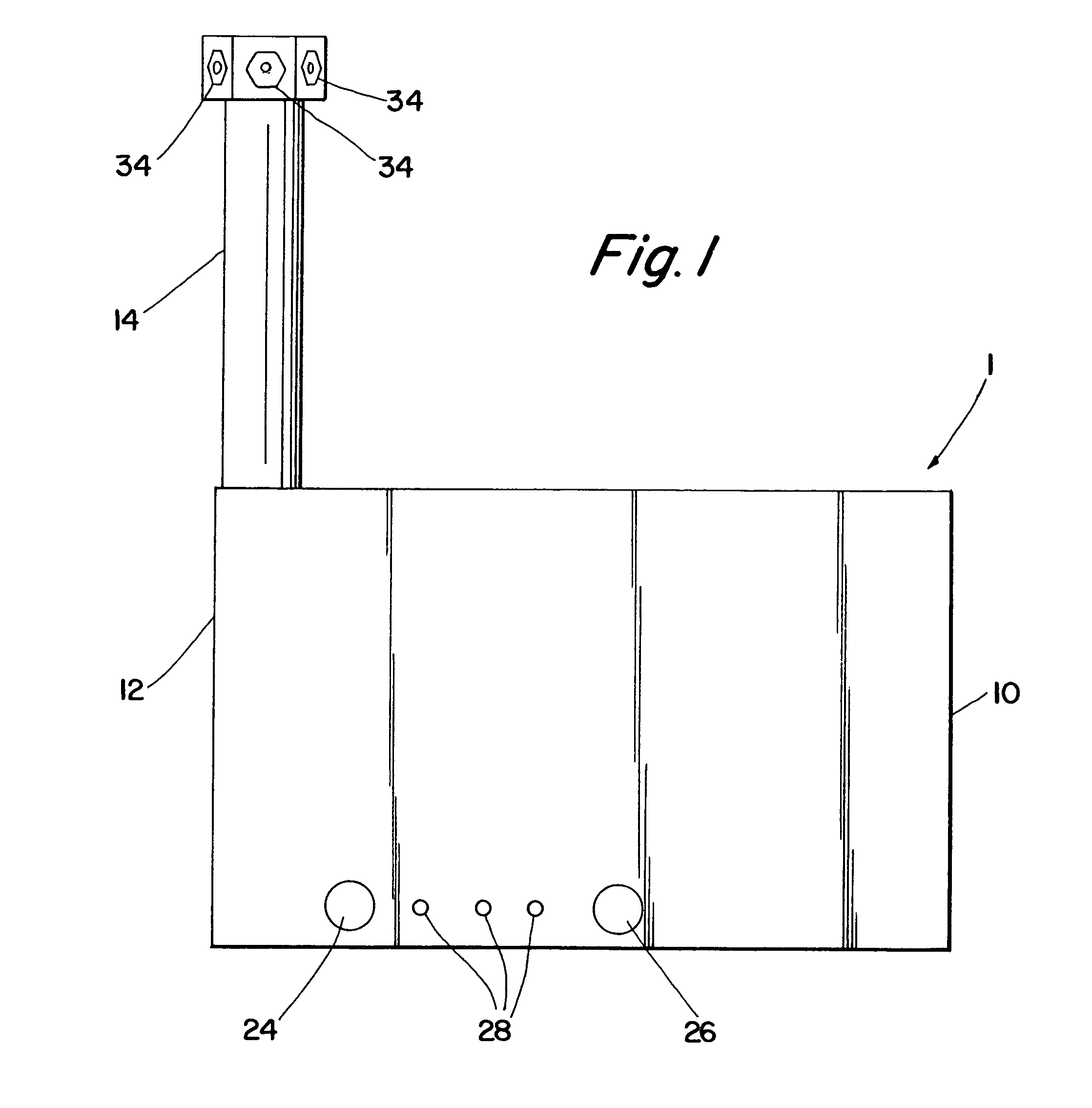
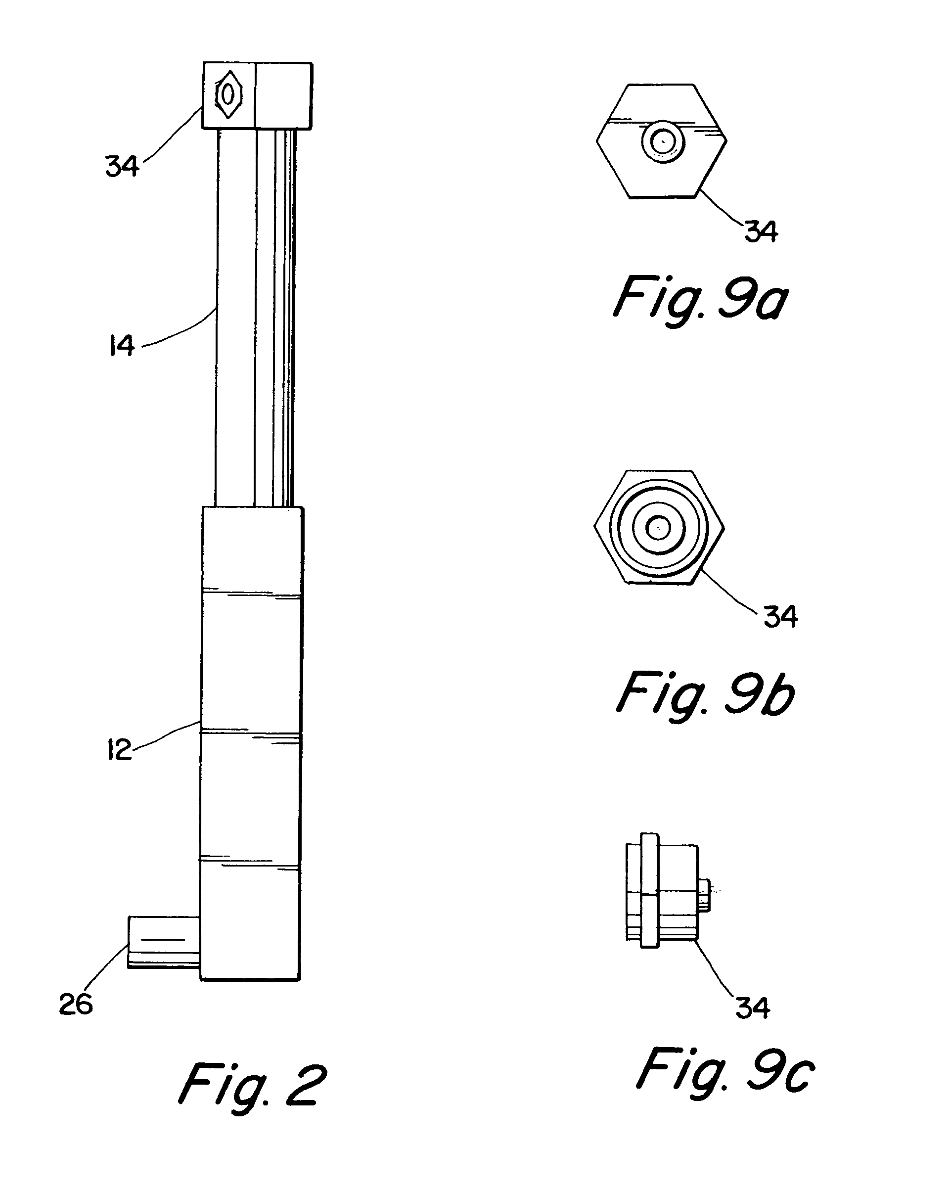
[0038]In a preferred embodiment of the cold plate unit, the coolant system defines a cold plate portion and a tower portion, the cold plate portion including the primary inlet manifold and the primary outlet manifold and the tower portion including the secondary inlet manifold and ...


PUM

PropertyMeasurementUnit
lengthaaaaaaaaaa
lengthaaaaaaaaaa
lengthaaaaaaaaaa

Abstract

An apparatus for cooling at least one fluid includes separable cold plate and dispenser units. The cold plate unit includes a coolant system, a fluid system and a metallic unit. The coolant system defines a cold plate portion and a tower portion. The cold plate portion of the coolant system has a primary inlet manifold and a primary outlet manifold, and the tower portion has a secondary inlet manifold and a secondary outlet manifold. The coolant system further includes a first plurality of coolant line segments connecting the primary and secondary inlet manifolds and a second plurality of coolant line segments connecting the secondary and primary outlet manifolds. The fluid system also defines a cold plate portion and a tower portion, the portions being in heat exchange relationship with the coolant system. The metallic unit includes unitary cold plate and tower portions which respectively incorporate the cold plate and tower portions of the coolant system and fluid system. The dispenser unit also includes a coolant system, a fluid system and a metallic unit. The coolant system of the dispenser unit includes a dispenser inlet manifold and a dispenser outlet manifold. The coolant system of the dispenser unit further includes a plurality of coiled coolant lines. The fluid system is in heat exchange relationship with the coolant system, being disposed at least partially within the coiled coolant lines. The metallic unit of the dispenser unit incorporates the dispenser coolant system and fluid system.

Description

[0001]The present application is a divisional application of U.S. patent application Ser. No. 09 / 691,731, filed Oct. 18, 2000, now U.S. Pat. No. 6,553,782, which is a continuation of U.S. patent application Ser. No. 08 / 615,399, filed Mar. 14, 1996, abandoned, which is a continuation-in-part of U.S. patent application Ser. No. 08 / 531,568, filed Sep. 13, 1995, now U.S. Pat. No. 5,743,107, each of which is incorporated herein by reference.FIELD OF THE INVENTION[0002]The present invention relates to an improved apparatus for dispensing cooled fluids, in particular beverages such as beer.BACKGROUND OF THE INVENTION[0003]In most commercial establishments where beer is served, the beer is supplied in barrels or kegs. Beer, as herein used, refers to anyone of those carbonated alcoholic malt beverages that are commonly called beer, ale and stout. The kegs of beer are stored and let to cool in refrigerated cold rooms that are provided in most commercial establishments to store foodstuffs and ...

Claims


Application Information

Patent Timeline
Patent Type & Authority Patents(United States)
IPC IPC(8): B67D5/62B67D7/80B67D1/08F25D31/00F28D7/08
CPCB67D1/0862B67D1/0867F25D31/003F28D7/0016F28D7/08F28F1/22F28F9/02F28F21/084F28D7/082Y10T29/49396Y10T29/4935
Inventor KYEES, MELVIN
Owner MANITOWOC FOODSERVICE CO LLC
Why Eureka
Try Eureka