Airflow control for multiple-displacement engine during engine displacement transitions

a technology of displacement transition and airflow control, which is applied in the direction of electric control, machines/engines, output power, etc., can solve the problems of reducing compression work, and achieve the effect of reducing engine speed variation and reducing pressur

Active Publication Date: 2006-03-21
FCA US
View PDF23 Cites 12 Cited by
  • Summary
  • Abstract
  • Description
  • Claims
  • Application Information

AI Technical Summary

Benefits of technology

[0007]In accordance with another aspect of the invention, the method preferably further includes changing spark timing and the amount of fuel supplied to the cylinders that are to remain active after the transition, from a time not earlier than moving the throttle plate, to thereby roughly match engine output torque generated during the transition with the engine output torque immediately prior to initiating the transition, and to correlatively reduce engine speed variation that might otherwise occur during the transition. It is noted that retarding spark advantageously serves to reduce pressure in the cylinders about to be deactivated during the transition, with an attendant reduction in the resulting “negative” transient compression work required over the.

Problems solved by technology

This compression work typically diminishes over several engine cycles as the deactivated cylinders and piston ring packs begin to cool, and as a quantity of such trapped gases blows by the ring packs.

Method used


Image

  • Airflow control for multiple-displacement engine during engine displacement transitions
  • Airflow control for multiple-displacement engine during engine displacement transitions

Examples


Embodiment Construction

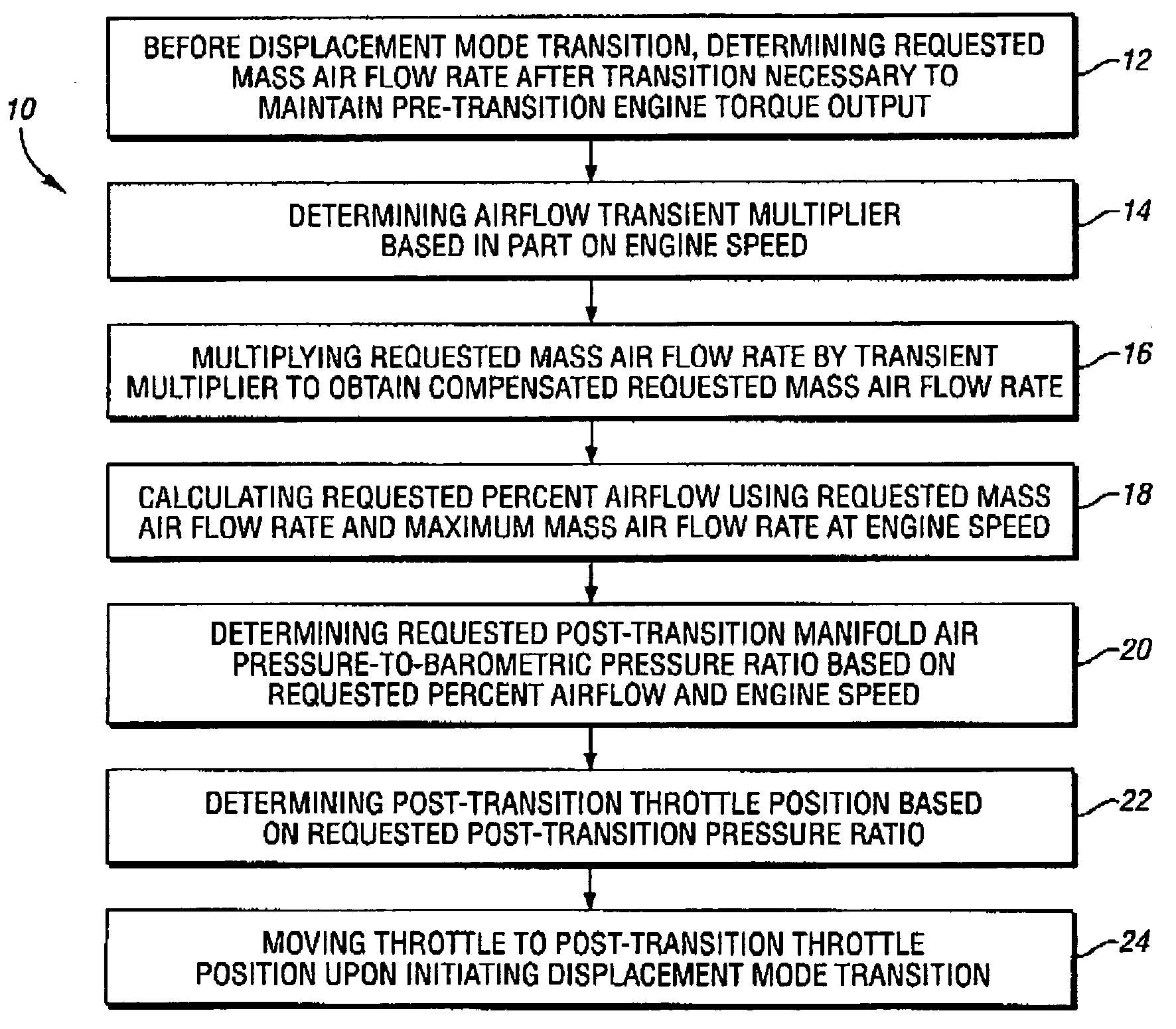
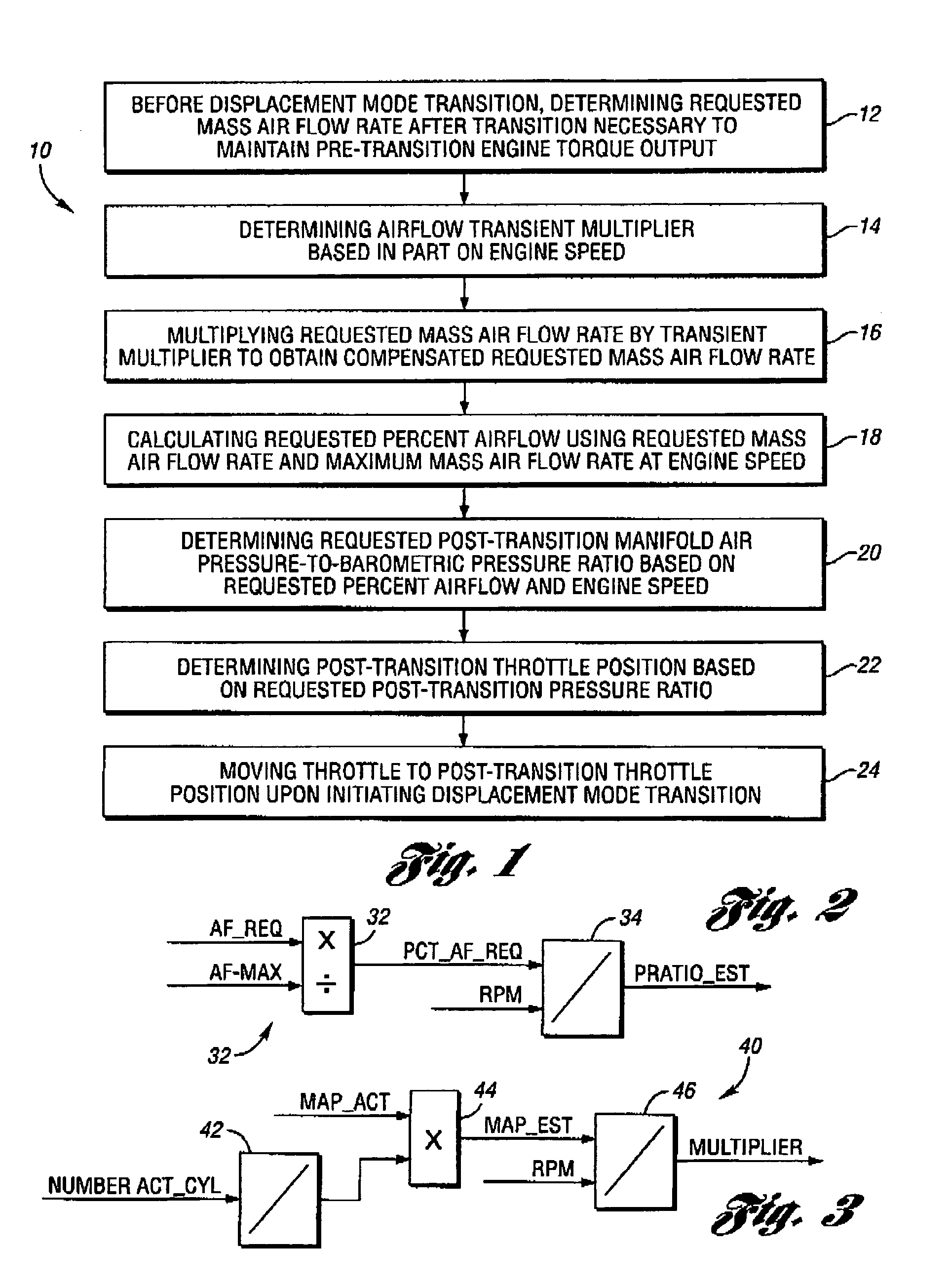
[0013]A method 10 for controlling airflow in an intake manifold of a multiple-displacement internal combustion engine during an engine displacement mode transition, for example, when transitioning between a full-displacement engine operating mode and a partial-displacement engine operating mode, is generally illustrated in FIG. 1. While the invention contemplates any suitable hydraulic and / or electro-mechanical systems for deactivating the given cylinder, including deactivatable valve train components, an exemplary method is used in controlling airflow in an eight-cylinder engine in which four cylinders are selectively deactivated through use of deactivatable valve lifters as disclosed in U.S. patent publication No. U.S. 2004 / 0244751 A1, the teachings of which are hereby incorporated by reference.

[0014]As seen in FIG. 1, the method 10 generally includes determining, at block 12, before a displacement mode transition, a requested post-transition mass air flow rate that will maintain ...


PUM


Abstract

A method for controlling airflow in an intake manifold of a multiple-displacement engine during an engine displacement mode transition includes determining, before a displacement mode transition, a post-transition mass air flow rate necessary to maintain a pre-transition engine torque output, as well as an airflow transient multiplier based on engine speed and an estimated post-transition manifold air pressure. After multiplying the requested mass air flow rate with the transient multiplier, the resulting compensated requested mass air flow rate is divided by a maximum mass air flow rate to obtain a requested percent airflow. The percent airflow is thereafter used with engine speed to determine a requested post-transition manifold air pressure-to-barometric pressure ratio, for example, using a lookup table; and the requested post-transition pressure ratio is used to determine a transient post-transition throttle position, to which an engine throttle will be moved upon initiating the displacement mode transition.

Description

FIELD OF THE INVENTION[0001]The invention relates generally to methods for controlling the operation of a multiple-displacement internal combustion engine, for example, used to provide motive power for a motor vehicle.BACKGROUND OF THE INVENTION[0002]The prior art teaches equipping vehicles with “variable displacement,”“displacement on demand,” or “multiple displacement” internal combustion engines in which one or more cylinders may be selectively “deactivated,” for example, to improve vehicle fuel economy when operating under relatively low-load conditions. Typically, the cylinders are deactivated through use of deactivatable valve train components, such as the deactivating valve lifters as disclosed in U.S. patent publication No. U.S. 2004 / 0244751 A1, whereby the intake and exhaust valves of each deactivated cylinder remain in their closed positions notwithstanding continued rotation of their driving cams. Combustion gases are thus trapped within each deactivated cylinder, whereup...

Claims


Application Information

Patent Timeline
Patent Type & Authority Patents(United States)
IPC IPC(8): F02D13/04
CPCF02D41/10F02D41/18F02D41/2409F02D2200/704F02D2200/0408
Inventor PRUCKA, MICHAEL JOHL, GREGORY LLI, ZHONGDUTY, MARK JDIVALENTIN, EUGENIOBONNE, MICHAEL A
Owner FCA US
Why Eureka
Try Eureka