Aerosol spray texture apparatus for a particulate containing material
- Summary
- Abstract
- Description
- Claims
- Application Information
AI Technical Summary
Benefits of technology
Problems solved by technology
Method used
Image
Examples
first embodiment
III. First Embodiment
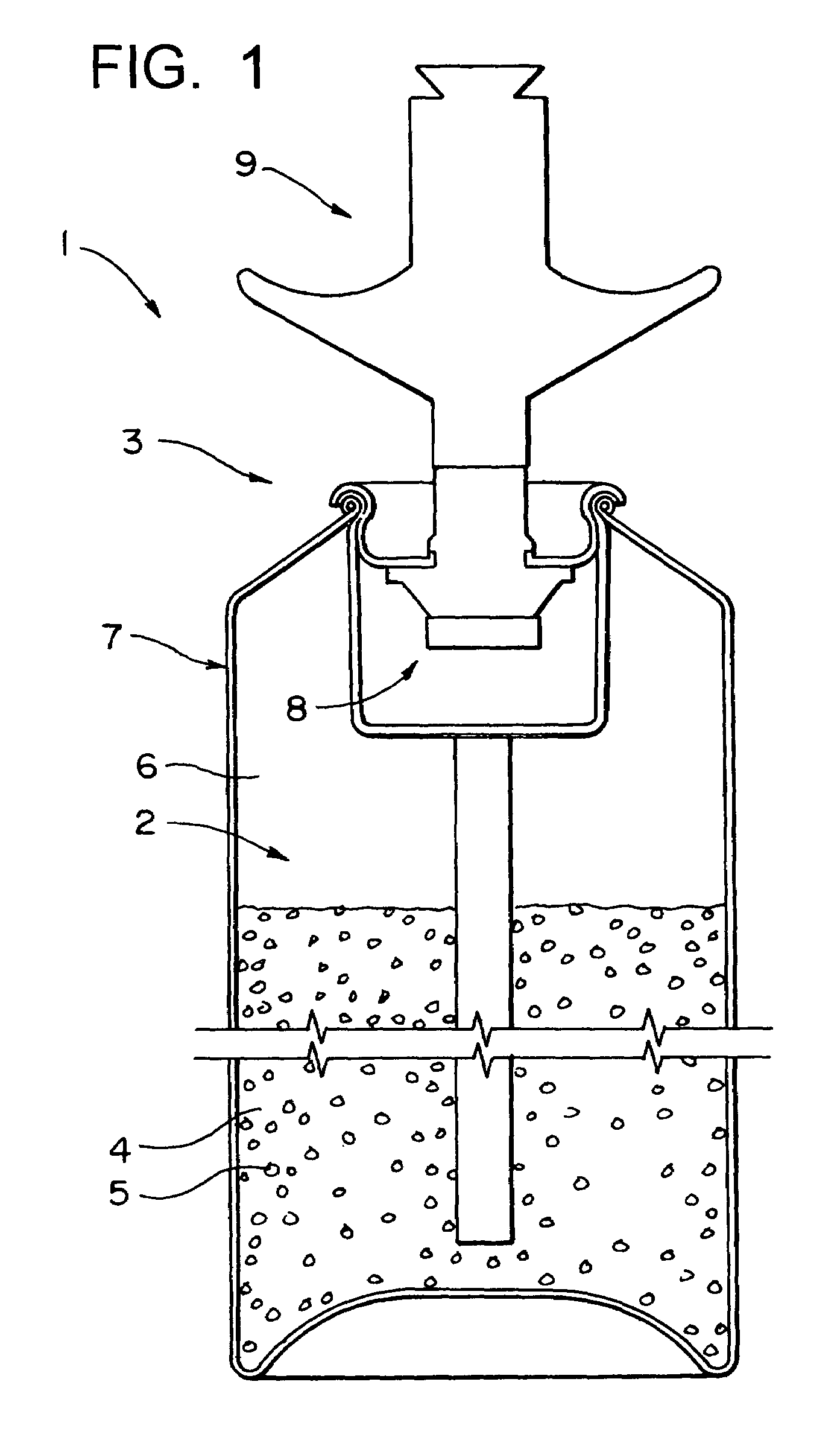
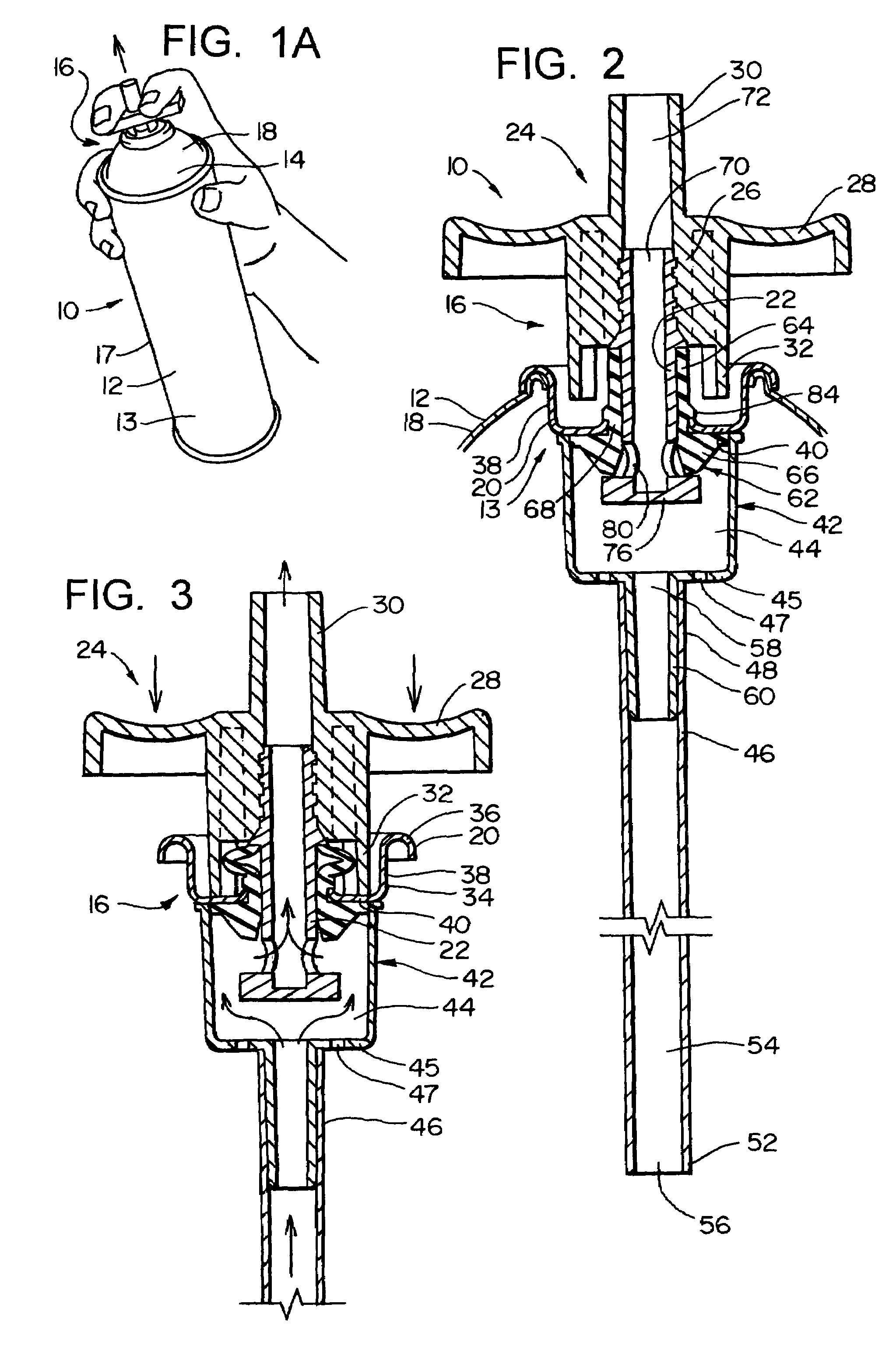
[0115]In FIG. 1A, it can be seen that the apparatus 10 of the present invention comprises an aerosol container 12 defining a main pressure chamber 13, and having at its upper end 14 a valve assembly 16. The container 12 has an overall cylindrical configuration, comprising a cylindrical sidewall 17, a top wall 18 (either integral with the sidewall 17 or made separately), and a bottom wall (not shown for ease of illustration). The valve assembly 16 is mounted at the center of the top wall 18.
[0116]The valve assembly 16 comprises a valve housing 20 mounted to the top container wall 18, and a valve stem or element 22 positioned within the housing 20 for movement between the closed position of FIG. 2 to the open position of FIG. 3. Fixedly attached to the upper end of the valve element 22 is a manually operable actuating and discharge portion 24, comprising a mounting portion 26, a cross bar 28, a discharge nozzle 30 extending upwardly from the mounting portion of 26...
second embodiment
IV. Second Embodiment
[0132]A second embodiment of the present invention is shown in FIG. 4. This is substantially the same as the first embodiment, except that the vent openings (designated 47a) are positioned in the sidewall of the housing 42a so that these direct flow laterally into the chamber 44a at the location of the intake openings 80a. It is surmised that this location of the vent openings 47a are able to be oriented to effect a tangential swirling pattern, or oriented more radially to provide a more direct force, in the vicinity of the openings 80a to enhance proper movement of the particles.
[0133]FIG. 5 is an enlarged view giving in inches the dimensions of a prototype built in accordance with the teachings of the present invention, and also to show the components more clearly. It is to be recognized, of course, that these dimensions could be increased or decreased within certain limits (e.g. ten percent, twenty percent, or possibly as high as fifty percent or higher, and ...
third embodiment
V. Third Embodiment
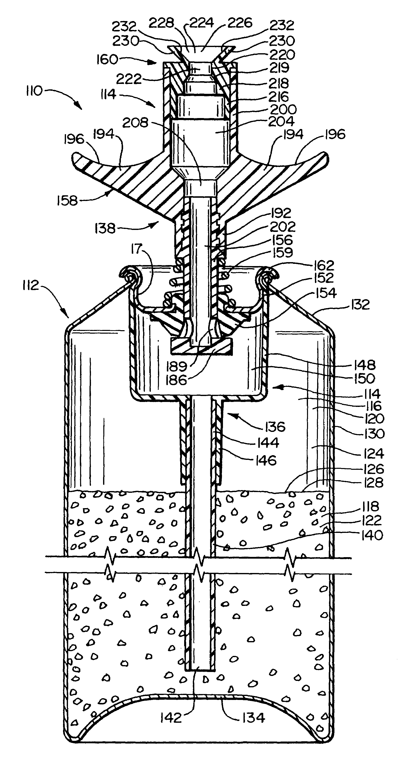
[0134]FIG. 6 illustrates at 110 of the a third embodiment of the present invention which is particularly adapted to apply an acoustic texture material to the surface of a ceiling. This apparatus 110 comprises a container 112 and a discharge assembly 114. The container 112 defines a chamber 116 having a texture material containing portion 118 and a propellant containing portion 120. In this third embodiment, the texture material containing portion 118 is located in the bottom part of the chamber 116 since the apparatus 110 is normally operated in a vertically aligned position so that the texture material 122 is positioned by gravity in the lower part of the chamber 116. The propellant containing portion 120 is in the upper part of the chamber 116, and the propellant 124 is a gaseous substance which is substantially inert, such as nitrogen or atmospheric air, relative to the texture material 122. There is a pressure interface 126 between the upper surface 28 of the ...
PUM
 Abstract
Description
Claims
Application Information
 - R&D
- Intellectual Property
- Life Sciences
- Materials
- Tech Scout
- Unparalleled Data Quality
- Higher Quality Content
- 60% Fewer Hallucinations
Browse by: Latest US Patents, China's latest patents, Technical Efficacy Thesaurus, Application Domain, Technology Topic, Popular Technical Reports.
© 2025 PatSnap. All rights reserved.Legal|Privacy policy|Modern Slavery Act Transparency Statement|Sitemap|About US| Contact US: help@patsnap.com


