Method for smoothing the surface of a gas turbine blade

a gas turbine blade and surface technology, applied in the direction of machines/engines, superimposed coating processes, manufacturing tools, etc., can solve the problem of inadmissible damage to the protective effect of the mcraly layer, and achieve the effect of smooth surface and efficient and cost-effectiv

Inactive Publication Date: 2006-03-21
SIEMENS AG
View PDF14 Cites 5 Cited by
  • Summary
  • Abstract
  • Description
  • Claims
  • Application Information

AI Technical Summary

Benefits of technology

[0009]An object of the present invention is to specify a method of smoothing the surface of a gas turbine blade. A method according to an exemplary embodiment of the present invention provides an especially efficient and cost-effective manner of smoothing a surface of a gas turbine blade, which leads to a sufficiently smooth surface of the gas turbine blade.
[0011]Therefore, it is proposed for the first time to smooth a gas turbine blade by a drag finishing method. It is surprisingly possible with such a drag finishing method to achieve qualitatively high-grade smoothing of the surface of the gas turbine blade in a very short time, to be precise without inhomogeneous material removal. Such inhomogeneous material removal would actually be expected in the case of such a drag finishing method on account of the complex and fluidically optimized shape of the turbine blade. In addition, such inhomogeneous material removal would locally impair the protective effect of the MCrAlY layer in an inadmissible manner.
[0015]This superimposition of movements ensures that the gas turbine blade is subjected to a homogenous abrasive process. The complex shape of the gas turbine blade, in particular the difference between the convex or concave shape of the suction or pressure side, there is the risk of nonuniform removal at the surface during the drag finishing. This is avoided by the described superimposition of movements, and thus in particular the surface shape, which is strictly predetermined aerodynamically, is maintained. A uniform layer thickness of an applied anticorrosion layer is thereby ensured.

Problems solved by technology

In addition, such inhomogeneous material removal would locally impair the protective effect of the MCrAlY layer in an inadmissible manner.

Method used


Image

  • Method for smoothing the surface of a gas turbine blade
  • Method for smoothing the surface of a gas turbine blade
  • Method for smoothing the surface of a gas turbine blade

Examples


Embodiment Construction

[0022]The same designations have the same meaning in the different figures.

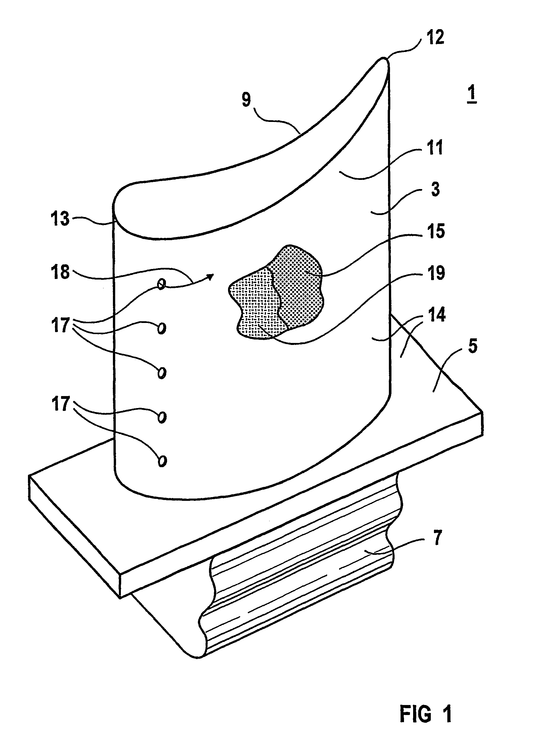
[0023]FIG. 1 shows a gas turbine blade 1 with an airfoil 3, a platform 5 and a blade root 7. The airfoil 3 has a pressure side 9 and a suction side 11, which adjoin one another at a leading edge 13 and a trailing edge 12. The airfoil 3 as well as that surface of the platform 5 which faces the airfoil 3 are provided with an anticorrosion layer 15. The anticorrosion layer 15 is a metal alloy of the class MCrAlY. Cooling passages 17 open out at the surface 14 of the airfoil 3.

[0024]During operation, the gas turbine blade 1 is subjected to a hot gas at a very high temperature. The anticorrosion layer 15 serves to protect against corrosion and oxidation by the hot gas. For use at especially high temperatures, a ceramic heat-insulating layer 19 may also be applied to the anticorrosion layer 15. In this case, the anticorrosion layer 15 also serves as an adhesive mediator layer between the parent body of the gas turb...


PUM

PropertyMeasurementUnit
angleaaaaaaaaaa
Raaaaaaaaaaa
roughnessaaaaaaaaaa

Abstract

A surface of the gas turbine blade is smoothed by way of a drag finish process. A first ring-shaped container is filled with a liquid abrasive medium. A second container which is arranged next to the first container is filled with a second liquid abrasive medium. A pivoting arm is arranged between and above the containers and can be pivoted along a pivoting direction. A drag device is arranged on the pivoting arm. The drag device leads a gas turbine blade on a carrier arm through the abrasive medium.

Description

[0001]This application is the national phase under 35 U.S.C. § 371 of PCT International Application No. PCT / EP01 / 13982 which has an International filing date of Nov. 29, 2001, which designated the United States of America and which claims priority on European Patent Application number EP 00128574.1 filed Dec. 27, 2000, the entire contents of which are hereby incorporated herein by reference.FIELD OF THE INVENTION[0002]The present invention generally relates to a method of smoothing the surface of a gas turbine blade, in particular, a surface of a gas turbine blade having an anticorrosion layer.BACKGROUND OF THE INVENTION[0003]DE-A-39 18 824 and U.S. Pat. No. 5,105,525 show a flatiron sole which has an especially scratch-resistant, readily slidable and easy-to-clean surface. The flatiron sole is coated with a nickel hard alloy and is ground and polished by a drag finishing method.[0004]A method of producing a coating on a gas turbine blade is described in U.S. Pat. No. 4,321,310. The...

Claims


Application Information

Patent Timeline
Patent Type & Authority Patents(United States)
IPC IPC(8): B24B1/00B24B31/10B24B19/14B24B31/00B24B51/00C23C4/08C23C4/18C23C28/00F01D5/28F02C7/00
CPCB24B1/00B24B51/00B24B31/003B24B19/14
Inventor BOLZ, ANDREAFELDHEGE, MARTIN
Owner SIEMENS AG
Why Eureka
Try Eureka