Direct current/direct current converter for a fuel cell system

a fuel cell and converter technology, applied in the direction of electrochemical generators, process and machine control, instruments, etc., can solve the problems of fuel cell power outages which are unacceptable, fuel cell is typically not able to respond immediately, and the quality of power or the regulation of the direct current (dc) bus is an issue, so as to reduce the topology of system cost and increase power conversion capability.

Active Publication Date: 2006-03-21
CONTINENTAL AUTOMOTIVE SYST INC
View PDF2 Cites 5 Cited by
  • Summary
  • Abstract
  • Description
  • Claims
  • Application Information

AI Technical Summary

Benefits of technology

[0009]An embodiment of the present fuel cell systems and control methods provides a DC / DC converter that utilizes one leg of an insulated gate bipolar transistor (IGBT) six pack module to provide bi-directional DC / DC conversion between a battery pack and an inverter DC bus. The other two legs of the IGBT six pack module provide DC / DC conversion between a fuel cell and the inverter DC bus. This achieves optimization of best use of the power stage to provide lower system cost topologies by utilizing the IGBT six pack module configuration. The battery pack can also supply power during fuel cell outages. One or two legs of the IGBT six pack module can be added in parallel to the battery leg by using a contactor or switch to increase power conversion capability.

Problems solved by technology

In an application utilizing an energy source, such as a fuel cell, the quality of power or the regulation of the direct current (DC) bus is an issue.
For example, a fuel cell is typically not able to respond immediately to peaks in demand.
A further issue in such an application is that the fuel cell may be subject to power outages which are unacceptable in an uninterruptible power supply (UPS) application.

Method used


Image

  • Direct current/direct current converter for a fuel cell system
  • Direct current/direct current converter for a fuel cell system
  • Direct current/direct current converter for a fuel cell system

Examples


Embodiment Construction

[0016]In the following description, certain specific details are set forth in order to provide a through understanding of various embodiments of the invention. However, one skilled in the art will understand that the invention may be practiced without these details. In other instances, well-known structures associated with electrical circuits and circuit elements have not been shown or described in detail to avoid unnecessarily obscuring descriptions of the embodiments of the invention.

[0017]Unless the context requires otherwise, throughout the specification and claims which follow, the word “comprise” and variations thereof, such as, “comprises” and “comprising” are to be construed in an open, inclusive sense, that is as “including, but not limited to.”

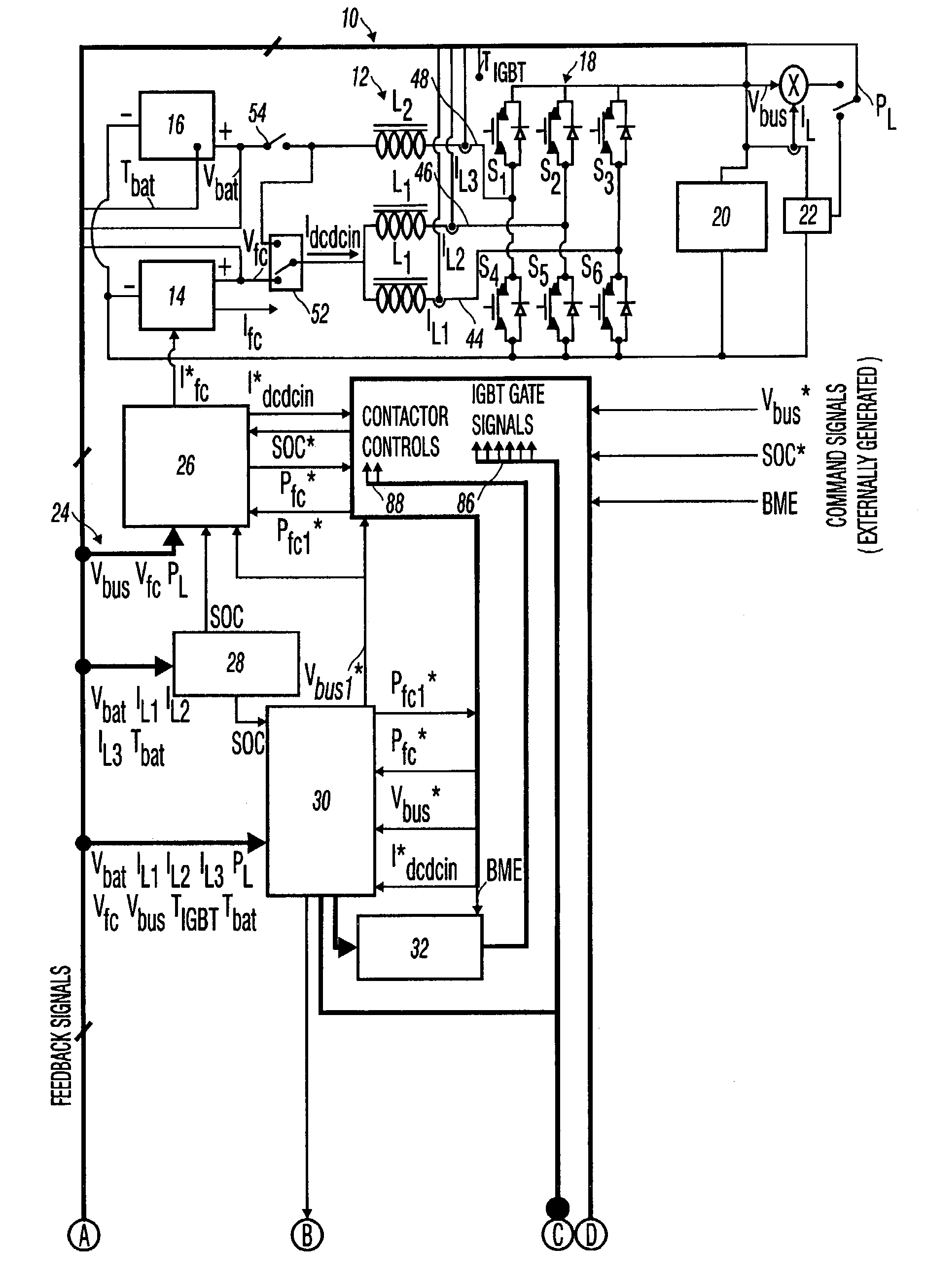
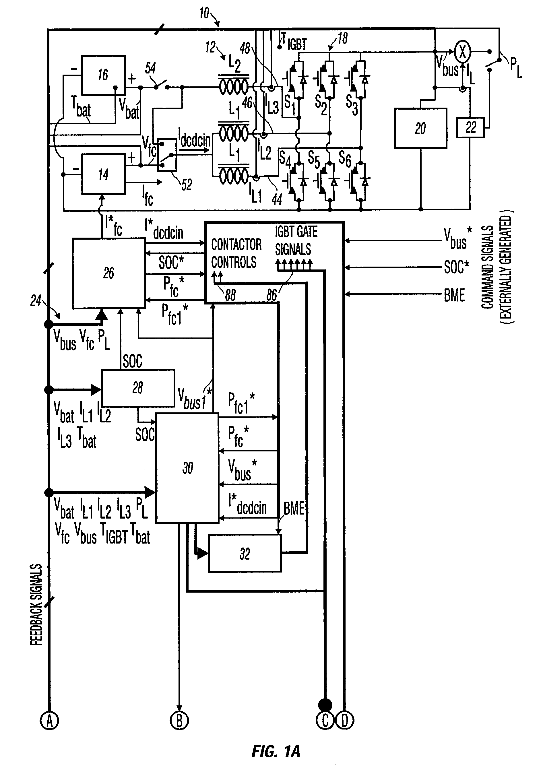
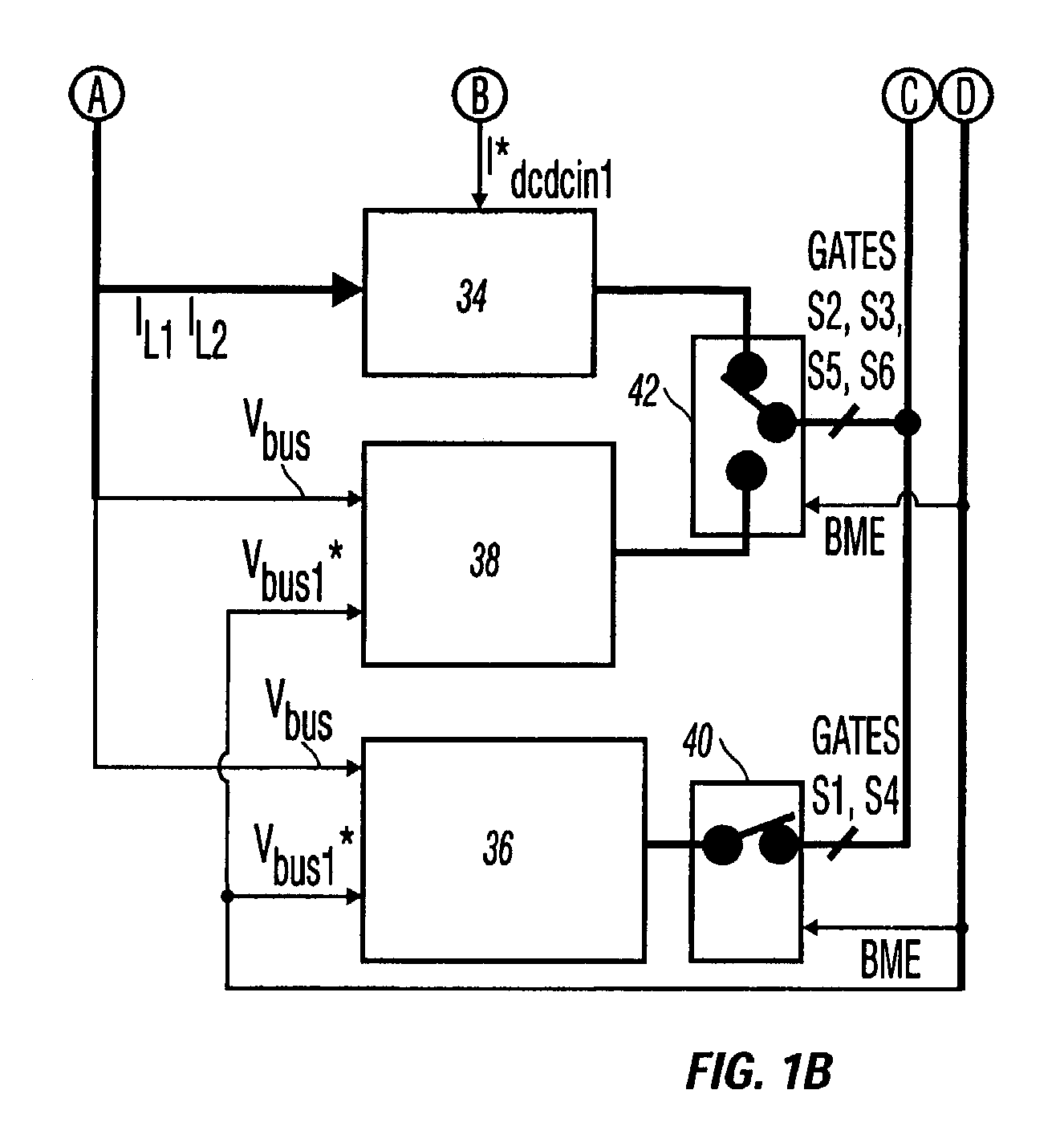
[0018]Referring now in detail to an embodiment of the fuel cell systems and control methods, an example of which is illustrated in the accompanying drawings, FIGS. 1A and 1B illustrate a circuit and control scheme for a fuel cell sys...


PUM

PropertyMeasurementUnit
output voltageaaaaaaaaaa
DC voltageaaaaaaaaaa
input currentaaaaaaaaaa

Abstract

Fuel cell systems and control methods including a fuel cell and a second energy source, such as a battery that is adapted to supplement the fuel cell. In addition, the fuel cell system utilizes a single bipolar switching module, such as an IGBT six pack module that is configured to implement a DC/DC converter, such as a DC/DC boost converter, for both the fuel cell and the battery. The fuel cell system also makes use of a controller that is configured to control either or both of input current and output voltage of the DC/DC converter.

Description

[0001]This Application is a non-provisional of 60 / 319,071 filed Jan. 16. 2002.BACKGROUND OF THE INVENTION[0002]1. Field of the Invention[0003]The present fuel cell systems and control methods relate generally to direct current-to-direct current (DC / DC) converters, and more particularly to using a DC / DC converter with both a fuel cell and a second energy source.[0004]2. Description of the Related Art[0005]In an application utilizing an energy source, such as a fuel cell, the quality of power or the regulation of the direct current (DC) bus is an issue. For example, a fuel cell is typically not able to respond immediately to peaks in demand. A further issue in such an application is that the fuel cell may be subject to power outages which are unacceptable in an uninterruptible power supply (UPS) application. There is a present need to address those issues, utilizing as many of the components of an existing power converter to implement a DC / DC converter with existing hardware and with ...

Claims


Application Information

Patent Timeline
Patent Type & Authority Patents(United States)
IPC IPC(8): H01M8/00H01M8/04H01M16/00
CPCH01M16/006H01M8/0488H01M8/04888H01M8/04917H01M8/04947H01M8/0491Y02E60/10Y02E60/50
Inventor KAMBOURIS, CHRISTOS A.BATES, JOHN T.
Owner CONTINENTAL AUTOMOTIVE SYST INC
Why Eureka
Try Eureka