Coating applied antenna and method of making same

a technology of coating applied to antennas and antennas, which is applied in the direction of resonant antennas, substantially flat resonant elements, and protective materials radiating elements, etc. it can solve the problems of inability to meet the design requirements of antennas, the material and shape of aircraft may not be compatible with antenna design requirements, and the efficiency of microstrip patch antennas at vhf/uhf, etc., to achieve low profile, light weight, and the effect of increasing bandwidth

Inactive Publication Date: 2006-03-21
UTI RECOVERY FUND
View PDF15 Cites 23 Cited by
  • Summary
  • Abstract
  • Description
  • Claims
  • Application Information

AI Technical Summary

Benefits of technology

[0011]It is another object of the invention to provide an antenna that can be applied to a substrate without causing structural or other physical damage to the substrate.

Problems solved by technology

Although using the aircraft structure as an actual part of the radiating antenna is very attractive, most of the time it is impractical.
Combining antenna installation and platform manufacture may simplify the fabrication process and reduce cost; however, the materials and shape of the aircraft may not be compatible with antenna design requirements.
However, a microstrip patch antenna is less efficient at VHF / UHF.
Also, microstrip antennas are inherently narrowband (only a few percent), making them unsuitable for most VHF / UHF communication applications.
Because of limited real estate on platforms such as aircraft, microstrip patch antennas are seldom used below 1 GHz.
In summary, patch antennas for frequencies below 1 GHz have very limited application in airborne systems.
Integrating them into the aircraft structure (so that they are part of the airborne platform) is technically very difficult, and does not offer any better performance or cost benefits.
However, conventional, flat panel PC board technology cannot be applied on sharply or double curved aircraft surfaces such as aircraft wings, aircraft body, etc.

Method used


Image

  • Coating applied antenna and method of making same
  • Coating applied antenna and method of making same
  • Coating applied antenna and method of making same

Examples


Embodiment Construction

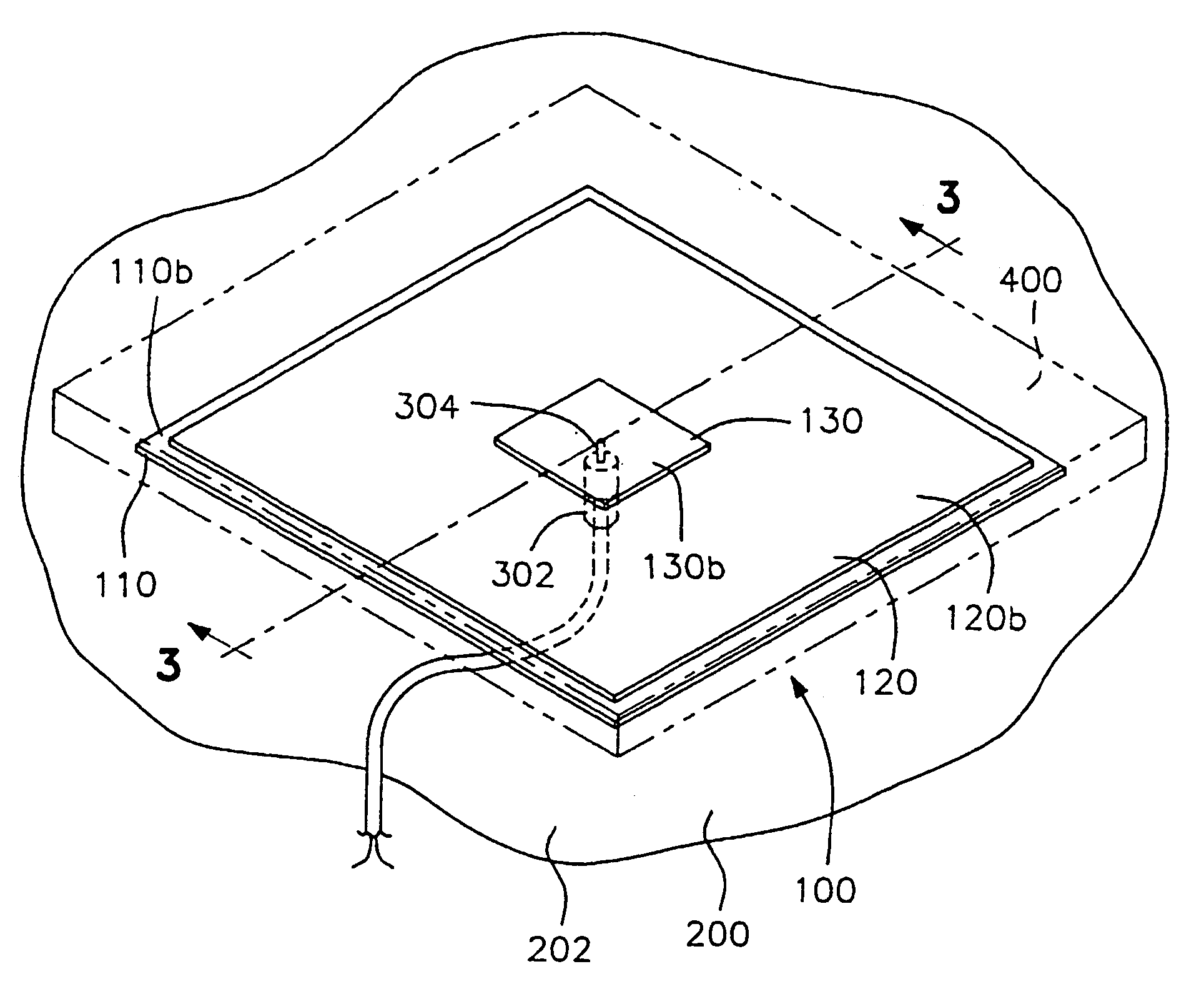
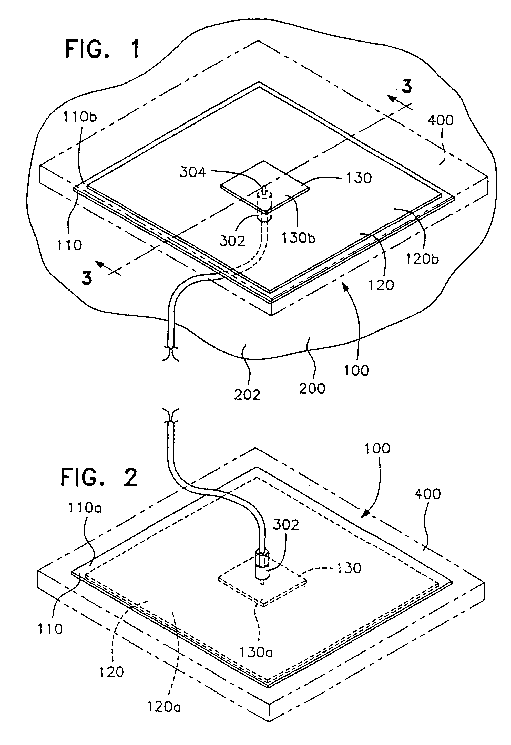
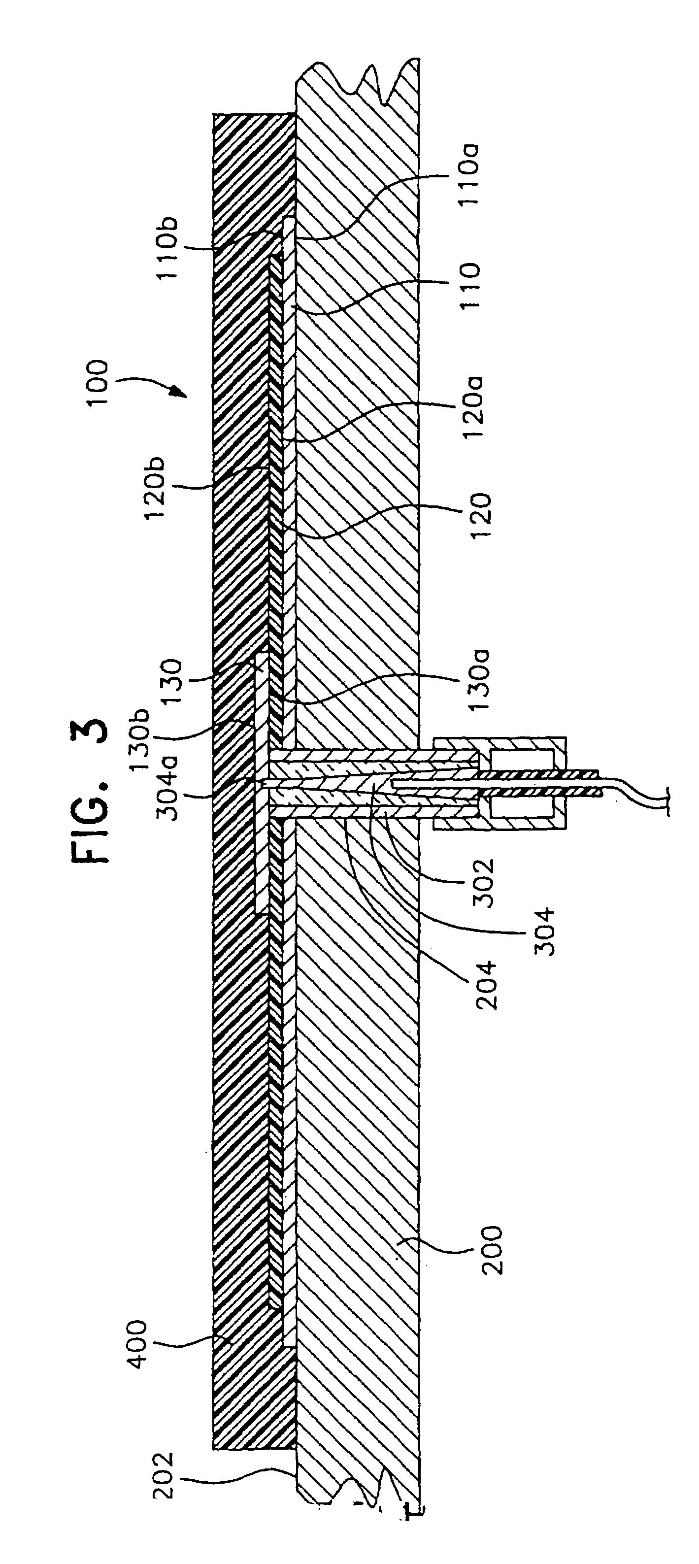
[0028]In describing preferred embodiments of the present invention illustrated in the drawings, specific terminology is employed for the sake of clarity. However, the invention is not intended to be limited to the specific terminology so selected, and it is to be understood that each specific element includes all technical equivalents that operate in a similar manner to accomplish a similar purpose.

[0029]Referring now to FIGS. 1–3, there is shown an antenna 100 in accordance with the present invention applied to an outer surface of a substrate structure 200 such as a curved aircraft surface, particularly a sharply or double curved surface such as an aircraft wing, body, etc, as well as on internal communication systems platforms such as ships, aircraft, building structures, etc. The substrate structure 200 can be made of materials such as aluminum, steel, metal alloys, composite structures, fiber reinforced plastics, polycarbonate, acrylic, polyethylene, polypropylene, fiberglass, e...


PUM


Abstract

An antenna (100) applied to a structure (200), the antenna (100) comprising a series of conductive and dielectric coatings. A conductive coating backplane or ground plane (110) is applied to a substrate structure (200), a non-conductive dielectric coating (120) is applied over the outer surface of the conductive coating backplane or ground plane (202), and a conductive coating patch, microstrip array or radiating element (130) is applied over the outer surface of the dielectric coating (120b). The pin of a coaxial cable (304) extends through the conductive coating backplane (110), the dielectric coating (120), and the conductive coating patch (130), for transmission of a signal from the antenna (100). The method allows for the non-destructive application of antennas on existing platforms for receiving and transmitting electromagnetic signals.

Description

[0001]This application claims priority to provisional U.S. Application Ser. No. 60 / 330,653 filed Oct. 26, 2001.[0002]This is a nationalization of PCT / US02 / 34132 filed Oct. 25, 2002 and published in English.FIELD OF THE INVENTION[0003]The present invention relates to coating-applied antennas and the method of making the same. More specifically, the invention relates to a coating-applied antenna that employs a conductive coating in place of the metal parts of a conventional antenna and a dielectric coating for the dielectric layer of a conventional antenna.BACKGROUND OF THE INVENTION[0004]The military has a need for low profile, low cost, low maintenance antennas that can be flush mounted on various types of land, air, and water platforms, including but not limited to tanks, aircraft, ships, and even articles of clothing. Low profile phased arrays are currently offered by the aircraft industry. Low profile mechanical scanned antennas, which provide wider scan coverage at a much lower ...

Claims


Application Information

Patent Timeline
Patent Type & Authority Patents(United States)
IPC IPC(8): H01Q1/38H01Q1/28H01Q1/40H01Q9/04
CPCH01Q1/28H01Q1/38H01Q9/0407H01Q9/045H01Q1/40Y10T428/254
Inventor BOYD, ROBERT C.LEGRANDE, WAYNE B.
Owner UTI RECOVERY FUND
Why Eureka
Try Eureka