Boiler system and method of controlling a boiler system

a technology of boiler system and boiler system, which is applied in the direction of machines/engines, steam generation using hot heat carriers, lighting and heating apparatus, etc., can solve the problems of significant degrading of boiler efficiency, serious damage to downstream systems supplied by boilers, and high cos

Inactive Publication Date: 2006-03-28
LAIR LIQUIDE SA POUR LETUDE & LEXPLOITATION DES PROCEDES GEORGES CLAUDE
View PDF4 Cites 22 Cited by
  • Summary
  • Abstract
  • Description
  • Claims
  • Application Information

AI Technical Summary

Benefits of technology

[0015]The present invention additionally advantageously provides a method of controlling a boiler system, where the method includes providing, within a first flow, at least one heat exchanger conduit fluidly connecting a first manifold to a second manifold, and where the second manifold is provided at an elevation above the first manifold.

Problems solved by technology

Additionally, if the liquid phase level reaches the second manifold 442, the second fluid in the liquid phase may cascade into the other conduits and create a circular flow (counterclockwise in FIG. 4B) of liquid phase fluid within the boiler, which would significantly degrade the efficiency of the boiler.
This quenching causes a temporary interruption of vapor production, which can cause serious damage to downstream systems supplied by the boiler.
Such sensors are usually confronted by one or

Method used


Image

  • Boiler system and method of controlling a boiler system
  • Boiler system and method of controlling a boiler system
  • Boiler system and method of controlling a boiler system

Examples


Embodiment Construction

[0022]Embodiments of the present invention will be described hereinafter with reference to the accompanying drawings. In the following description, the constituent elements having substantially the same function and arrangement are denoted by the same reference numerals, and repetitive descriptions will be made only when necessary.

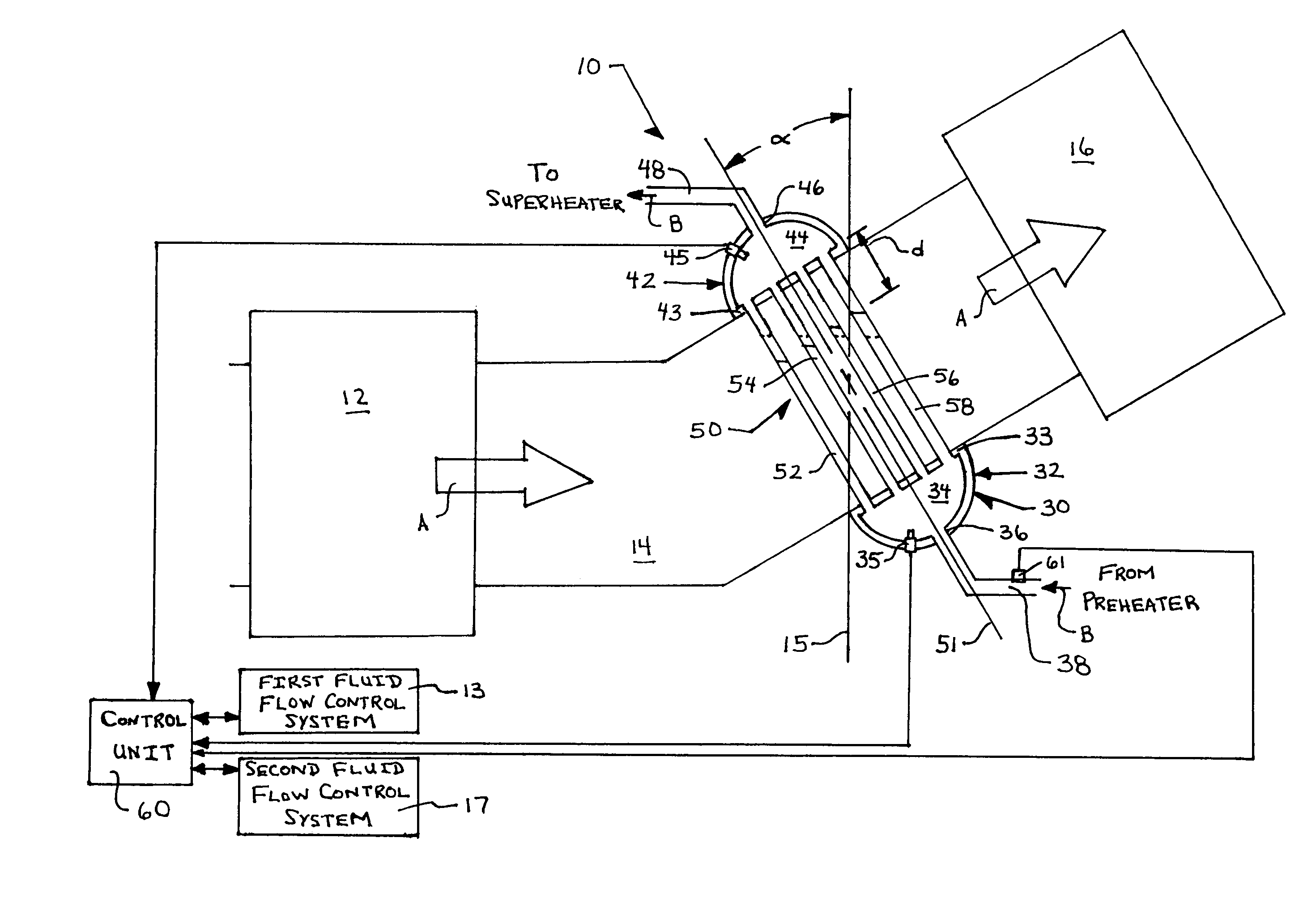
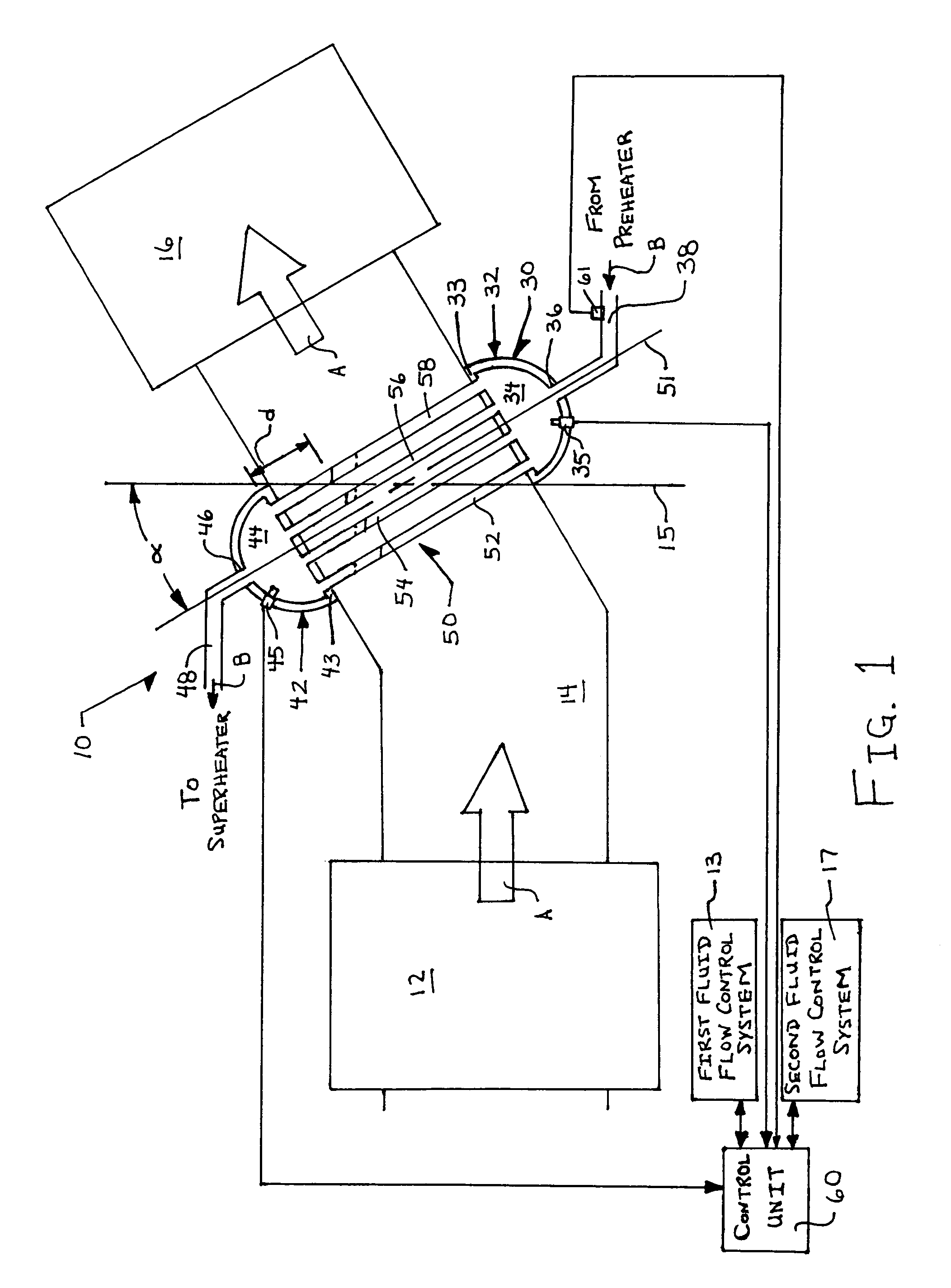
[0023]FIG. 1 is a schematic view of an embodiment of a boiler system 10 according to the present invention incorporated in a superheated vapor generation system. FIG. 1 generically depicts a superheating heat exchanger or superheater 12 having a flue 14 that carries a heated first fluid flow (represented by arrows A) discharged from the superheater 12. The superheater can be directly-fired or indirectly fired. The flue 14 carries the first fluid flow A through the boiler of the present invention, and then optionally to an additional heat exchanger 16, which can be, for example, a preheater or economizer used to preheat a second fluid flow. Although the arr...


PUM


Abstract

A boiler system including a first manifold, a second manifold provided at an elevation above the first manifold, and a heat exchanger conduit fluidly connecting the first and second manifolds. The conduit is provided within a first fluid flow, and the heat exchanger conduit receives a second fluid. A thermocouple is provided within the second manifold to measure a temperature of the second fluid within the second manifold. A control unit is provided to maintain a level of liquid phase of the second fluid such that liquid phase of the second fluid does not enter the second manifold based on the temperature measured by the thermocouple. The boiler system can be provided with first and second conduits, where the second conduit is provided within the first fluid flow downstream of the first conduit, and where the first and second conduits are inclined with respect to a vertical axis.

Description

BACKGROUND OF THE INVENTION[0001]1. Field of the Invention[0002]The present invention relates generally to heat exchangers and methods of controlling heat exchangers.[0003]2. Discussion of the Background[0004]Boilers are utilized as heat exchangers in numerous applications. Boilers typically utilize heat transfer liquid within a tube to absorb heat from an outside source, and then transfer a substantially liquid-free vapor fraction of the heated fluid to a desired location for use. The heated fluid within the boiler is typically in both a gaseous phase and a liquid phase. Boilers are particularly advantageous for use in a configuration in which it is desired to prevent the presence of heat transfer fluid in a liquid phase at a location downstream of the boiler.[0005]A related art boiler 430 is depicted in FIGS. 4A and 4B. The boiler 430 is provided along a flue 414. The boiler 430 includes a first manifold 432, a second manifold 442 provided at an elevation directly vertically above...

Claims


Application Information

Patent Timeline
IPC IPC(8): F22B21/02
CPCF22B1/02F22B21/02F28F27/02F28D1/05341F28D2021/0064
Inventor LOMAX, JR., FRANKLIN D.HEFFERNAN, THOMAS J.NASSER, KHALIL M.LETTOW, JOHN S.
Owner LAIR LIQUIDE SA POUR LETUDE & LEXPLOITATION DES PROCEDES GEORGES CLAUDE
Why Eureka
Try Eureka