
Electric motor vehicle with passenger opening through ring motor

a technology of electric motors and ring motors, which is applied in the direction of electric vehicles, passenger vehicle superstructures, propulsion by batteries/cells, etc., can solve the problems of cumbersome battery replacement in emergencies, cumbersome vehicle weight reduction, and difficulty in creating extra space for accumulators, so as to reduce the number of wheels, increase the diameter, and provide more torque

Inactive Publication Date: 2006-03-28
PAL ANADISH KUMAR
View PDF9 Cites 25 Cited by
  • Summary
  • Abstract
  • Description
  • Claims
  • Application Information

AI Technical Summary

Benefits of technology

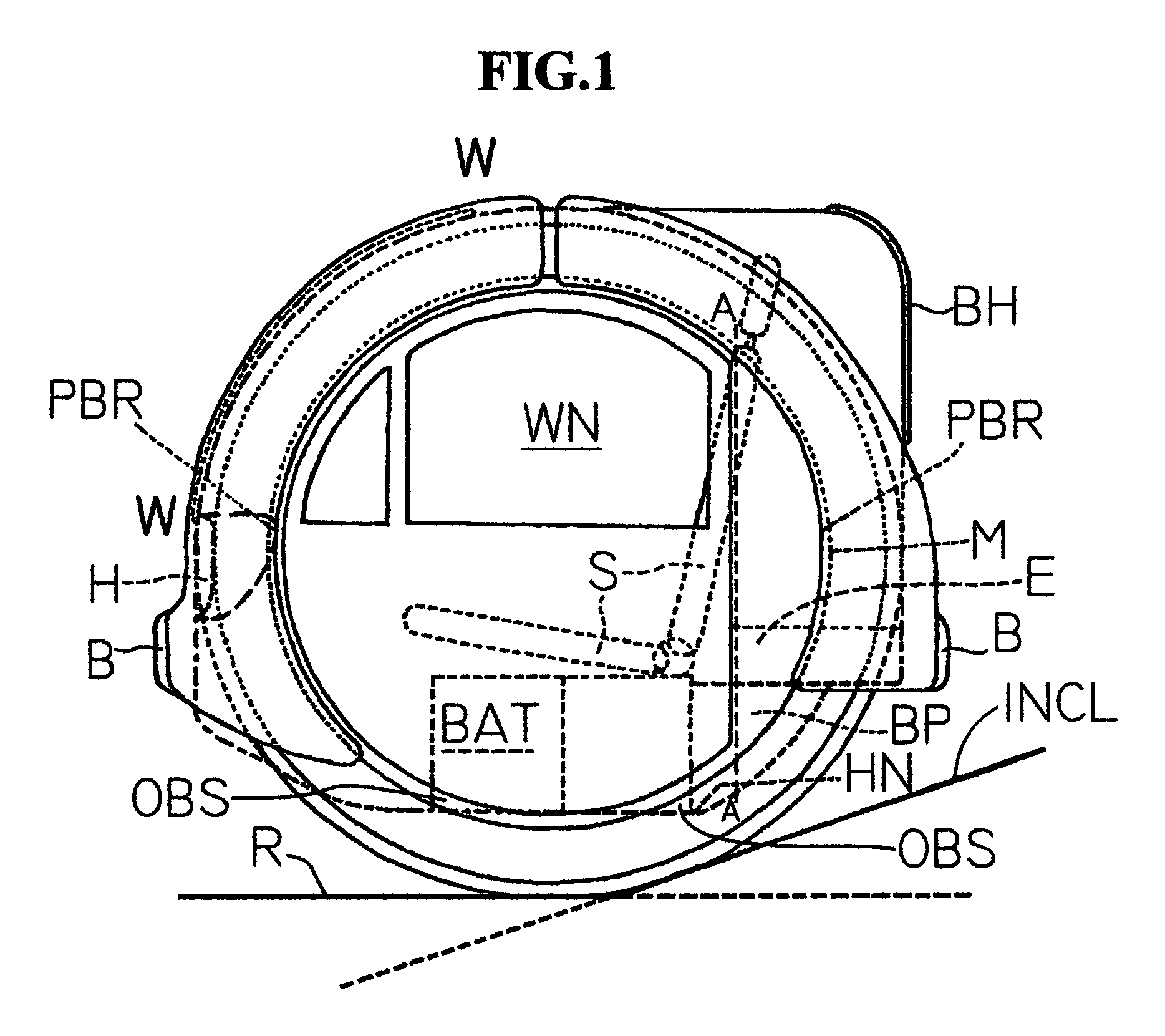
[0008]This invention fully avoids the earlier problems by increasing the diameter and reducing the number of wheels. Ring-like or annulate wheels, two in number, get integrated with the vehicle body of the electric motor vehicle of the present invention, doing away with the conventional axle. The large diameter of a toroidal electric motor integrated with the annulate wheel, provides more amount of torque at slow speeds without using any gears. The vehicle body of this electric motor vehicle is basically in the font of a cylinder, the circular side of which faces the surface on which the vehicle travels; both the ends of the cylinder remain vertical, and these two ends also act as openings. The two annulate wheels are mounted near the two ends, one on either side. The hub of the annulate wheel houses the permanent-magnet toroidal rotor, while the toroidal stator with low-voltage windings is mounted on the basically cylindrical body of the electric motor vehicle, which acts as the axle for both the annulate heels. In principle, this electric motor vehicle is built inside an enlarged and hollowed out axle. The source of electric power possibly in the form of electrical energy storage devices are kept near that surface of the vehicle body the other side of which always faces the ground; this positioning of the electrical energy storage devices acting as the source of electric power, makes the center of gravity of the electric motor vehicle low and lends stability to the design—this is possible, because all the electrical energy storage devices like accumulators and superconductor assemblies are heavy. The two toroidal electric motors one on either annulate wheels, have individual drives controlled by electrical and / or electronic processing units for running the two toroidal electric motors and also effecting regenerative braking when needed. Steering is accomplished by differential rotation of the two annulate wheels. An electronic communication link between two or more such vehicles would enable all-thus-linked vehicles to travel as a train of identical vehicles, main steering being done by the vehicle on the front; this will simulate the present-day multi-wheel modes of transport, with the ease of detachability and flexibility.
[0009]Thus, this invention avoids the use of gears, a mechanical steering, suspensions and pneumatic tires; it has a much greater torque generation, compared to other motor-the-wheel designs. The rolling coefficient of friction is small, because the chord-versus-the-wheel-circumference ratio at the ground contact is low due to the increased effective diameter of the annulate wheel (which is more like a hub). This invention helps to increase the effective traveling range of an electrical vehicle with this novel structural design. As the source of electric power is placed at a level close to the ground, replacing them is easier compared to many existing designs of electric motor vehicles. With efficiency, simplicity and flexibility, this invention may be the harbinger of the imminent advent of a truly electrical motor vehicle.

Problems solved by technology

But then there was this need to have a sizeable number of accumulators which, of course, would weigh down the vehicle considerably.
It was difficult to create extra space for the accumulators; and changing the batteries in case of emergencies was cumbersome.
This tended to increase the rolling friction between the wheels and the road surface, as the ratio between the chord which forms at the road contact and the circumference of the tire increases with increasingly smaller wheels.
It is a major drawback for electric-vehicle design; reducing the range of the vehicle for a full battery charge.
But as there are no gears in the case of a direct-driven wheel motor, in order to generate high torques, either the diameter or the thickness of the wheels have to be increased: This makes the wheels heavy.

Method used


Image

  • Electric motor vehicle with passenger opening through ring motor
  • Electric motor vehicle with passenger opening through ring motor
  • Electric motor vehicle with passenger opening through ring motor

Examples


Embodiment Construction

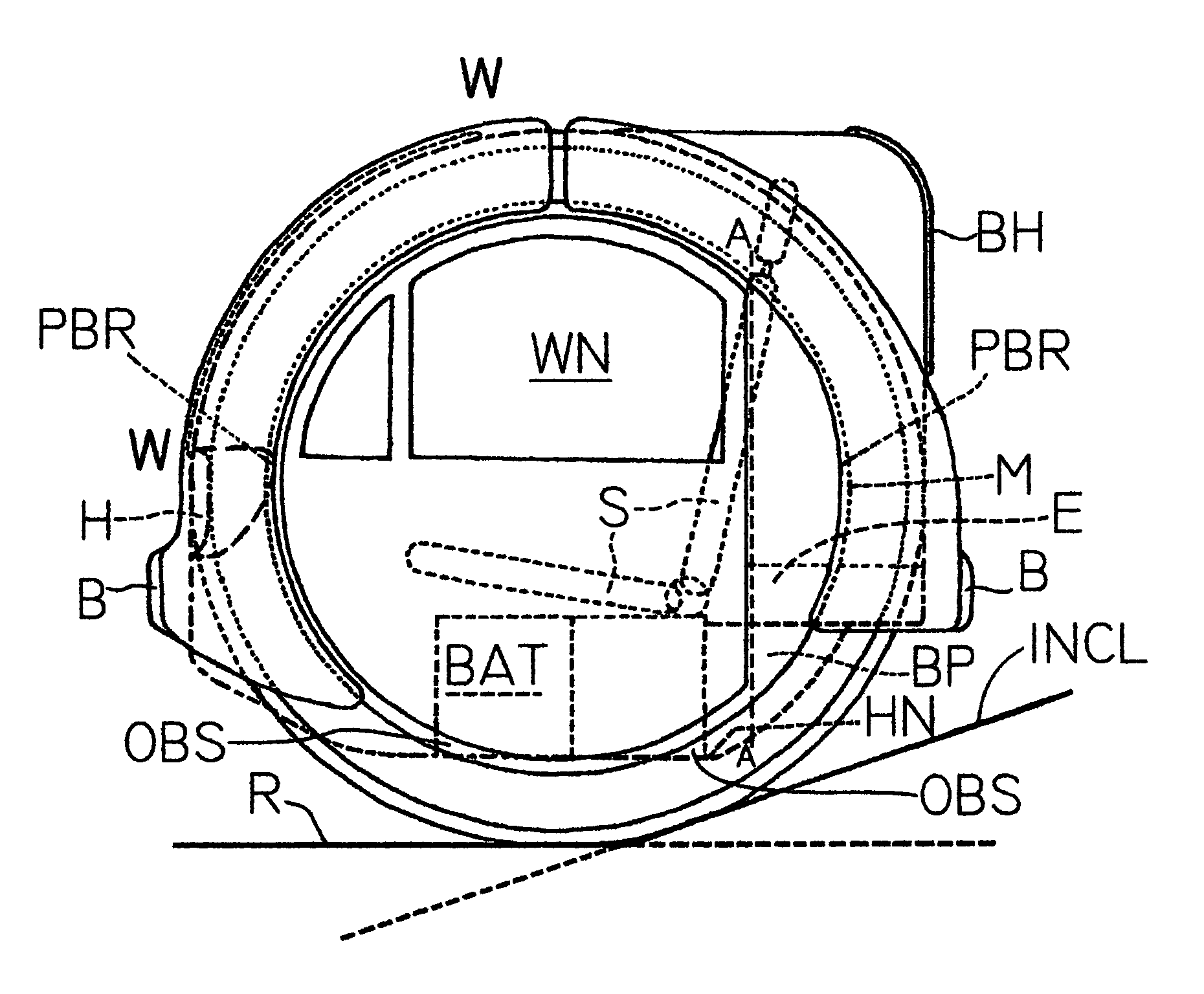
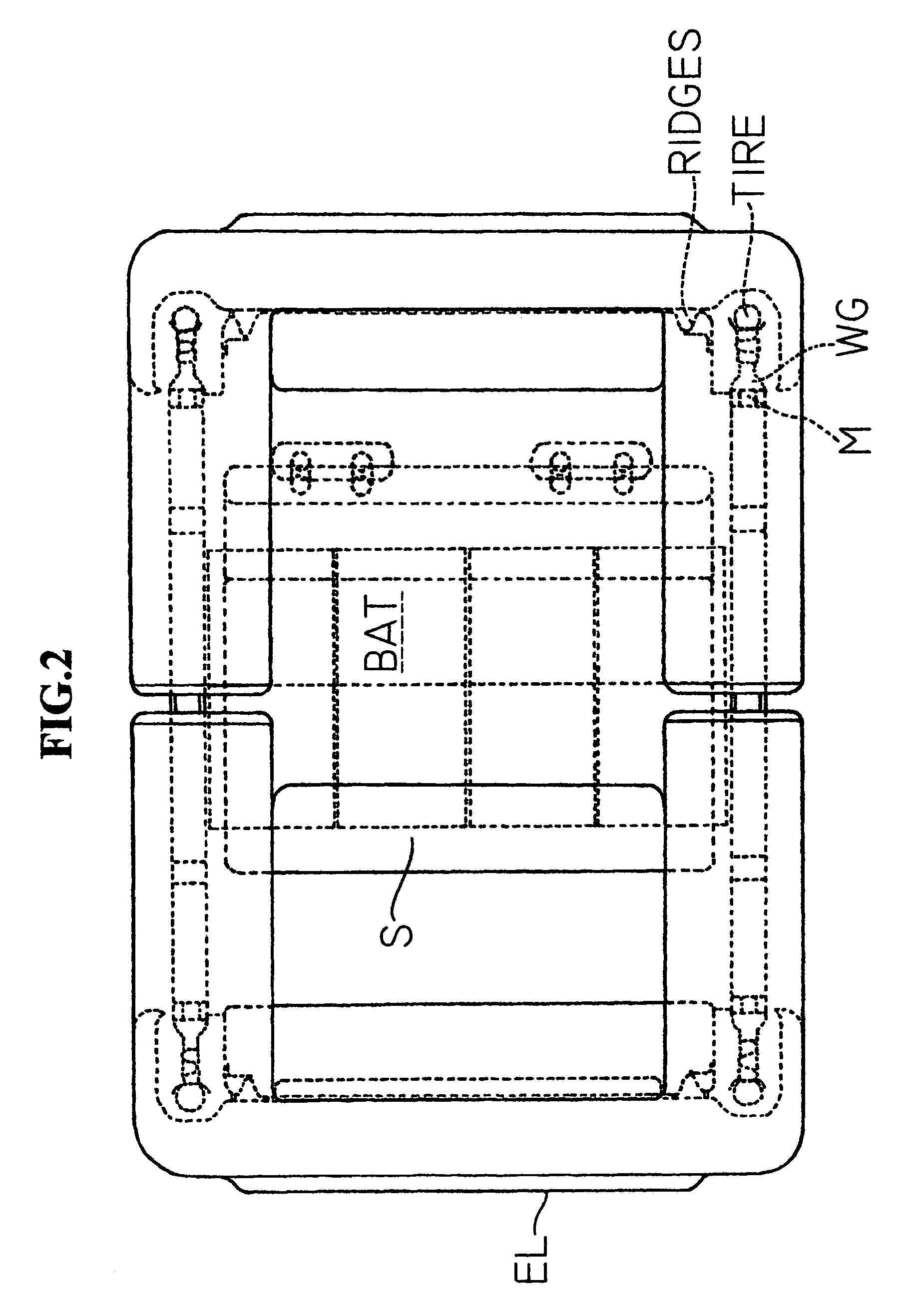
[0014]FIG. 1 shows the side view of the vehicle. The total height of the vehicle is nearly 50 inches. In this present form, it is designed to accommodate two persons with some luggage space at the back. The seats are marked S. The batteries, the source of electric power in this embodiment of the present invention, are placed below seats S, in battery enclosure BAT (FIG. 1, FIG. 2 and FIG. 3). There is a provision for keeping four lead acid batteries of 200AH, 12V rating. The total weight of the batteries is 240 kgs. The position of battery enclosure BAT keeps the center of gravity of the vehicle very low, this, coupled with the eccentric loading on the vehicle, provides stability to the vehicle, in spite of its having only two parallel annulate wheels. The batteries could be placed in two arrangements. One is side by side, so that the batteries could be taken out from the direction of BP in FIG. 1. Battery protector BP is made of material having good impact strength, capable of with...


PUM


Abstract

A two-wheel electric vehicle with ringlike, large, powered parallel wheels, in which at least one ringlike wheel is driven by a large toroidal electric motor. The fully circular rotor of the large toroidal electric motor is integrated with the hub of the ringlike wheel, while the circular or semi-circular toroidal stator is joined to the body of the two-wheel electric vehicle, the ringlike wheel and the toroidal electric motor having a common bearing. The electric power source to drive the toroidal electric motor is located near the ground-facing portion of the vehicle body. An opening is formed in the internal circular area of the toroidal stator, to allow the entry and exit of the passengers of the vehicle. A similar small vehicle with parallel, coaxial wheels allows the occupant of the small vehicle to travel, seated either facing the conventional front or the rear of the small vehicle.

Description

CROSS-REFERENCE TO RELATED APPLICATIONS[0001]Provisional application No. 60 / 182,772, filed on Feb. 14, 2000.STATEMENT REGARDING FEDERALLY SPONSORED RESEARCH OR DEVELOPMENT[0002]Not ApplicableREFERENCE TO A MICROFICHE APPENDIX[0003]Not ApplicableBACKGROUND OF THE INVENTION[0004]Most of the contemporary electrically driven motor vehicles are designs which have been standardized with an internal-combustion machine as the power pack. As the internal-combustion engine runs best at an optimum rpm, and structurally has to be in a cubic form, the need to have gears and a lot other mechanical parts is always there.[0005]While switching over to an electric-drive principle to run a motor vehicle, the first efforts had been to replace the internal-combustion engine with a high-rpm electric motor. But then there was this need to have a sizeable number of accumulators which, of course, would weigh down the vehicle considerably. It was difficult to create extra space for the accumulators; and chan...

Claims


Application Information

Patent Timeline
IPC IPC(8): B62D61/00B60K7/00B62K1/00
CPCB60K7/0007B62D61/00B62K1/00B60K2007/0046B62D31/003B60K2007/0092B60L50/51Y02T10/70Y02T10/64
Inventor PAL, ANADISH KUMAR
Owner PAL ANADISH KUMAR
Learn More