Method and device for pulse rate detection

a pulse rate and detection method technology, applied in the field ofsignal processing, can solve the problems of reducing the comfort of users, affecting the accuracy of pulse rate detection, so as to reduce the standard deviation of the detected heart rate, avoid overfitting, and high robustness and accuracy

Inactive Publication Date: 2006-03-28
MENDEL BIOTECHNOLOGY INC +1
View PDF11 Cites 222 Cited by
  • Summary
  • Abstract
  • Description
  • Claims
  • Application Information

AI Technical Summary

Benefits of technology

[0014]It is thus a principal object of the present invention to provide a device and method for accurately monitoring and detecting heart rate based on photoplethysmography, even under intense physical activity.
[0015]More particularly, an object of the present invention is to provide a solution that allows for adequate removal of ambient light and motion contributions in the optical signals.
[0020]According to the present invention, an accurate motion detecting device is used to provide a reliable motion reference signal. This motion detecting device is preferably a fully integrated three dimensional accelerometer which exhibits a high accuracy and very low noise.
[0022]Furthermore, in order to grasp the spatial diversity of the optical characteristics of the tissue, at least two optical sensors are used. This two-channel arrangement, associated with an adequate noise reduction algorithm (preferably an algorithm based on so-called spatio-temporal Principal Component Analysis or PCA), allows one to remove measurement noise and non-modelled stochastic signal contributions as well as reduce artefacts related to finger movements which are generally not recorded by the accelerometer and therefore not initially cancelled.
[0024]An assessment of the performance of the proposed solution according to the invention has shown its high robustness and accuracy. It has to be pointed out that the application of nonlinear instead of linear modelling decreases the standard deviation of the detected heart rate of about one to two percent. This is mainly due to the inclusion of the parsimonious MDL-based model selection, which avoids an overfitting of the time series. Indeed, the full nonlinear model would retain pulse related components in the estimate of the motion artefacts. Since these components are subtracted from the optical signals, the quality of the enhanced signal and consequently the reliability of the estimated pulse are reduced. In contrast, MDL selects only movement related parameters in the model, which yields higher enhancement performance and a more accurate pulse estimation in adverse noisy environments.

Problems solved by technology

The use of an external probe is often considered as a reduction of the user's comfort.
A reflection mode system typically has much poorer signal to noise ratio, resulting from the fact that a smaller proportion of the light which is not absorbed will be reflected than transmitted.
One of the main problems of PPG measurement is corruption of the useful signal by ambient light and other electromagnetic radiations (so-called light artefacts) and by voluntary or involuntary subject movement (so-called motion artefacts).
These artefacts lead to erroneous interpretation of PPG signals and degrade the accuracy and reliability of PPG-based algorithms for the estimation of cardiovascular parameters.
In contrast, processing of motion artefacts is a tough task since its contribution often exceed that of the useful pulse-related signal by an order of magnitude.
Motion artefacts are a particularly critical problem for the design of a wrist-located pulse detecting device.
This kind of approach allows one to reduce the occurrence of false alarms in clinical environments, but it often degrades the signals with small motion artefacts contributions.
This could lead to erroneous estimation of cardiovascular parameters.
Nevertheless, motion references are classically obtained by piezo-sensors or optical measures and convey therefore only incomplete or local information of motion.
This degrades the performance of model-based noise cancelling techniques since they require complete and low-noise motion reference signals.

Method used


Image

  • Method and device for pulse rate detection
  • Method and device for pulse rate detection
  • Method and device for pulse rate detection

Examples


Embodiment Construction

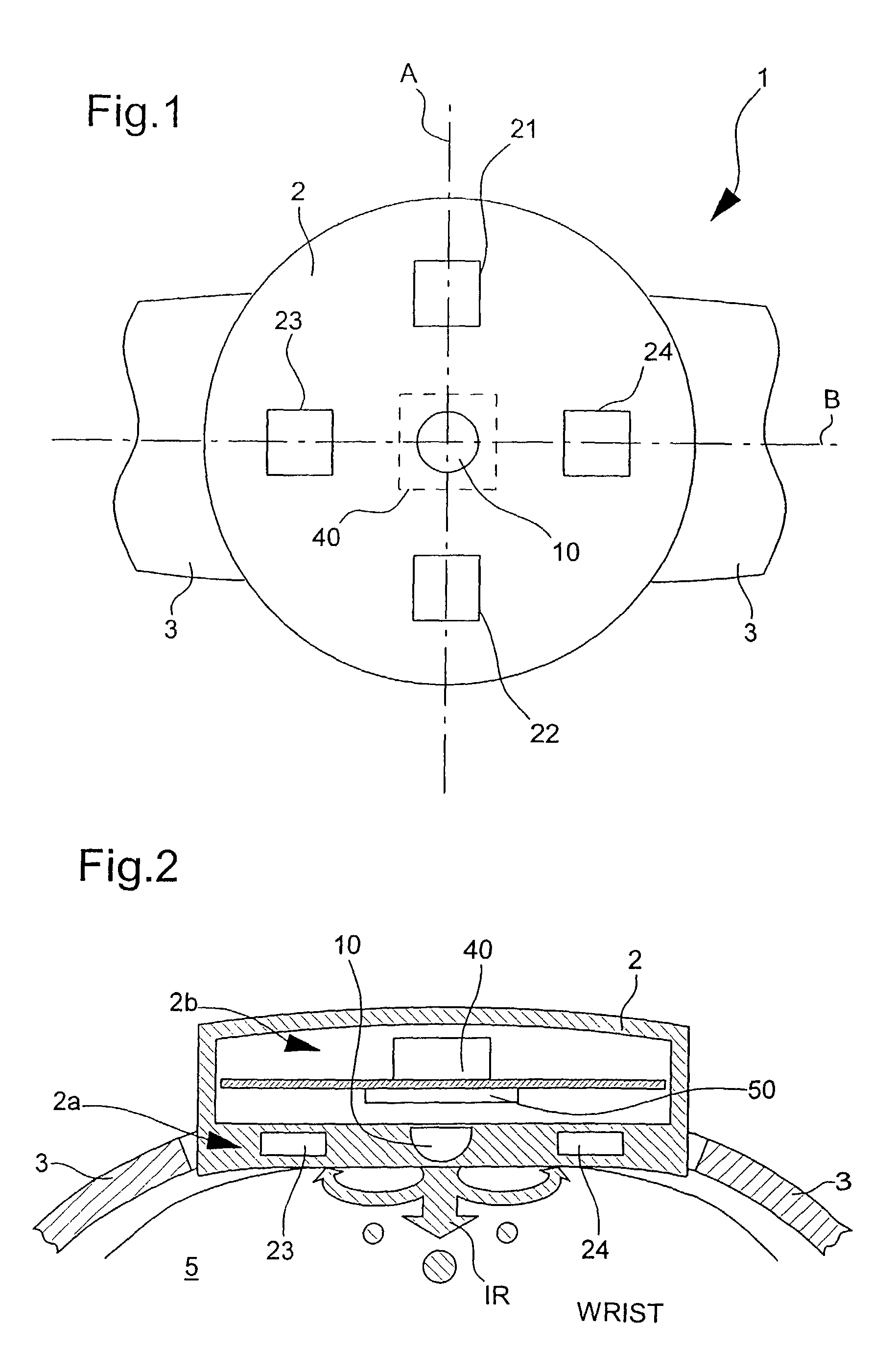
[0031]FIGS. 1 and 2 schematically show a top view of the bottom side and a side view of a wrist-located pulse rate detecting device, indicated globally by reference numeral 1, according to a preferred embodiment of the present invention.

[0032]While the invention will be described hereinbelow with respect to a portable device which is adapted to be worn on the wrist and which is based on the measurement of light reflected in the body tissue, it will be appreciated that the detecting device according to the present invention could be designed to be worn on other parts of the human body such as a patient's finger, nail, ear lobe or any other suitable member or part of the human body. In addition, the same principles could be applied to a detecting device based on the measurement of light transmitted through the body tissue (such as those typically used in pulse oximetry) where the signal to noise ratio is higher. In addition, these principles could be applied for pulse oximetry on the ...


PUM


Abstract

Portable pulse rate detecting device for contact with human body tissue, including a light-emitting source for emitting radiant energy directed at through human body tissue; at least first and second light detectors for detecting intensity of radiant energy after propagation through human body tissue and for providing first and second input signals as a function of such propagation, a detecting device for providing a motion reference signal, and processing means for removing motion-related contributions from the first and second input signals and subtracting a calculated model based on the motion reference signal from each of the first and second input signals, wherein the processing means is also for removing measurement noise and residual non-modeled contributions from the first and second enhanced signals using a noise reduction algorithm.

Description

FIELD OF THE INVENTION[0001]This invention is in the field of signal processing and is more specifically directed to pulse rate detection.BACKGROUND OF THE INVENTION[0002]Portable heart rate monitoring devices are classically composed of a processing device and an external probe (e.g. electronic stethoscope, optical measure at ear lobe, chest belt for electrocardiogram—ECG-based measurement, etc.). The use of an external probe is often considered as a reduction of the user's comfort. ECG-based pulse rate detecting devices using external electrode probes are for instance disclosed in documents U.S. Pat. Nos. 4,108,166, 6,018,677, 6,149,602 and WO 00 / 51680.[0003]Various pulse rate detection systems are known in the art. Pulse rate detection devices using pressure sensitive transducers such as piezoelectric elements are for instance disclosed in documents U.S. Pat. Nos. 3,838,684, 4,195,642, 4,331,154, 5,807,267 and WO 80 / 00912.[0004]More recently, measuring techniques based on so-call...

Claims


Application Information

Patent Timeline
Patent Type & Authority Patents(United States)
IPC IPC(8): A61B5/02A61B6/00A61B5/024
CPCA61B5/721A61B5/02416
Inventor VETTER, ROLFRENEVEY, PHILIPPEGENTSCH, ROLANDKRAUSS, JENSDEPEURSINGE, YVES
Owner MENDEL BIOTECHNOLOGY INC
Why Eureka
Try Eureka