Expandable spinal fusion device and methods of promoting spinal fusion

a fusion device and expandable technology, applied in the field of expandable osteogenic fusion devices, can solve the problems of affecting the normal anatomical function of the disc, affecting the complete fusion of the disc, and superfluous hardware used to maintain the stability of the spine,

Inactive Publication Date: 2006-03-28
WARSAW ORTHOPEDIC INC
View PDF44 Cites 661 Cited by
  • Summary
  • Abstract
  • Description
  • Claims
  • Application Information

AI Technical Summary

Benefits of technology

[0018]In the various embodiments of the present invention, the expandable implant maintains intervertebral disc space between adjacent vertebral bodies while providing a void intermediate the vertebral bodies where the bone growth inducing material may be packed, thereby minimizing the above-mentioned stress-shielding of bone material while enabling radiographic visualization of the developing fusion mass.

Problems solved by technology

Frequently, pathologies affecting the spinal disc can disrupt the normal anatomical function of the disc.
In the early history of these bone osteogenic fusion devices, the devices were formed of cortical-cancellous bone which was generally not strong enough to support the weight of the spinal column at the instrumented level.
With this technique, once fusion occurred across the vertebral bodies and incorporated the bone osteogenic fusion device, the hardware used to maintain the stability of the spine became superfluous.
Nevertheless, with some of the interbody fusion devices, there remains difficulty in achieving a complete fusion, at least without the aid of some additional stabilizing device, such as a rod or plate.
Moreover, some of the devices are not structurally strong enough to support some loads and bending moments applied at certain levels of the spine.
Further difficulty has been encountered when a surgeon, desiring to avoid removal of the spinal facet joints laterally, uses an undersized interbody fusion cage in a posterior lumbar interbody fusion procedure (PLIF).
Use of undersized devices results in sub-optimal contact with the endplates of adjacent vertebral bodies and consequent sub-optimal bone formation inside the device, and can lead to pseudoarthrosis.
Additionally, undersized devices may not provide adequate disc space distraction and nerve root decompression.
Due to the high degree of anatomical and physiological variation encountered in all surgery, efforts to avoid utilization of a posteriorly undersized implant can require the availability of numerous devices of different dimensions, and increase the time required to carry out the surgical procedure, thus increasing the cost and risk associated with the procedure.
Some prior efforts to address this difficulty through use of expandable devices have utilized designs involving numerous parts, or designs that apply excessive stress force to the device, resulting in device strain.
These design approaches increase the risk of mechanical failure.
Also, they may occlude the space between vertebral body endplates, inhibiting fusion from adequately occurring.
Even with devices that do not have the aforementioned difficulties, still other undesirable characteristics exist.
Studies have suggested that the interbody fusion implant devices, especially those implants of the “cage” design, lead to stress-shielding of bone material within the cage.
The stress-shielding phenomenon relieves some or all of the load applied to the bone material to be fused, which can greatly increase the time for complete bone fusion, or disturb the quality and density of the ultimately formed fusion mass.
A further difficulty encountered with many fusion implants is that the material of the implant is not radiolucent.
Thus, the spinal surgeon does not have adequate means to determine the progress of the fusion, and in some cases cannot ascertain whether the fusion was complete and successful.
Thus, the field of spinal fusion lacks a suitable intervertebral fusion device that can be made small enough to facilitate insertion in the intervertebral space and support bone growth material within the intervertebral space and expand to maintain the normal height of the disc space.
Further, current spinal fusion devices do not sufficiently reduce the risk of stress-shielding the fusion mass and do not enable visualization of the fusion mass as the arthrodesis progresses.

Method used


Image

  • Expandable spinal fusion device and methods of promoting spinal fusion
  • Expandable spinal fusion device and methods of promoting spinal fusion
  • Expandable spinal fusion device and methods of promoting spinal fusion

Examples


first embodiment

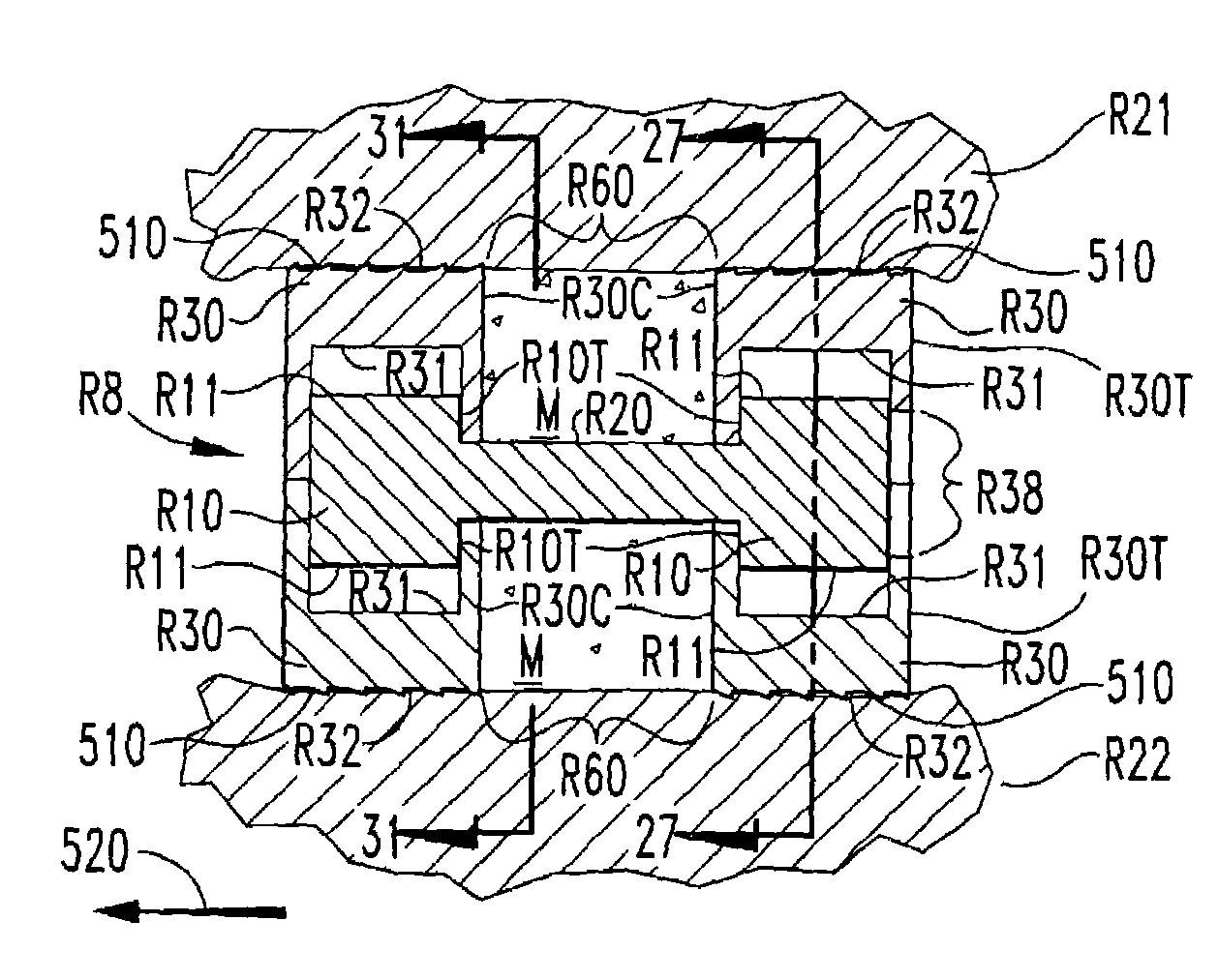
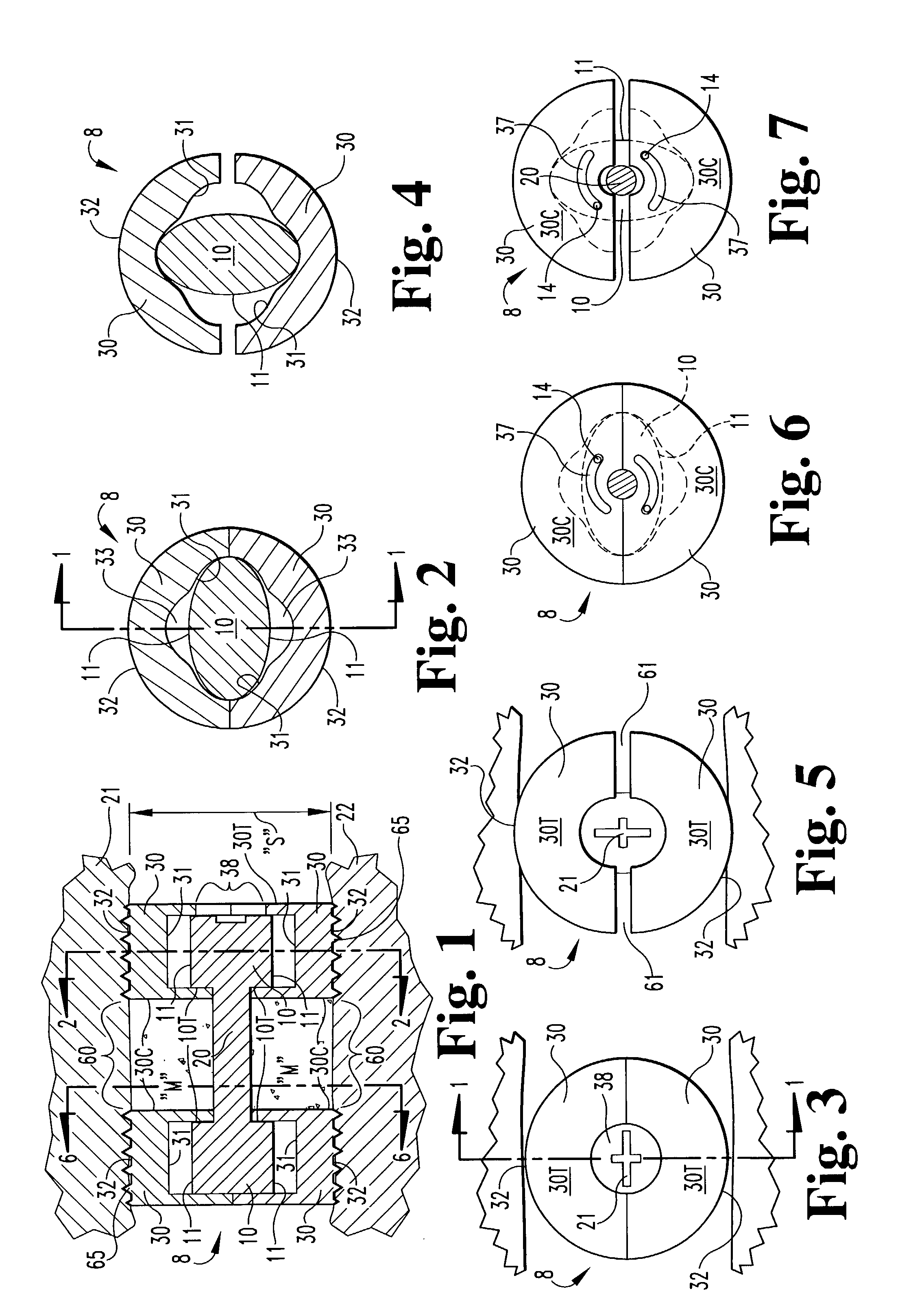
[0048]In accordance with the present invention, an expandable osteogenic fusion implant 8, depicted in FIGS. 1–7, has a cam-action expansion member. Implant 8 includes cams 10 connected at opposite ends of a connecting member 20, and two end members 30, respectively, enclosing each cam. Cams 10 have an outer surface that contacts a first portion of the inner surface of each of the ends 10 when the implant is not expanded, but when rotated as in FIG. 4, the cams 10 contact a second portion of each of the end members 30. The end members 30 further include exterior surfaces 32 that contact the endplates of the vertebral bodies 21 and 22, respectively, above and below the disc space “S” of FIG. 1 when the implant is in an expanded configuration. Exterior surfaces 32 may include a bone engaging configuration 65, such as threads or ridges to promote a secure positioning of the implant or to enable insertion of the implant. The implant transforms from the non-expanded configuration to the ...

third embodiment

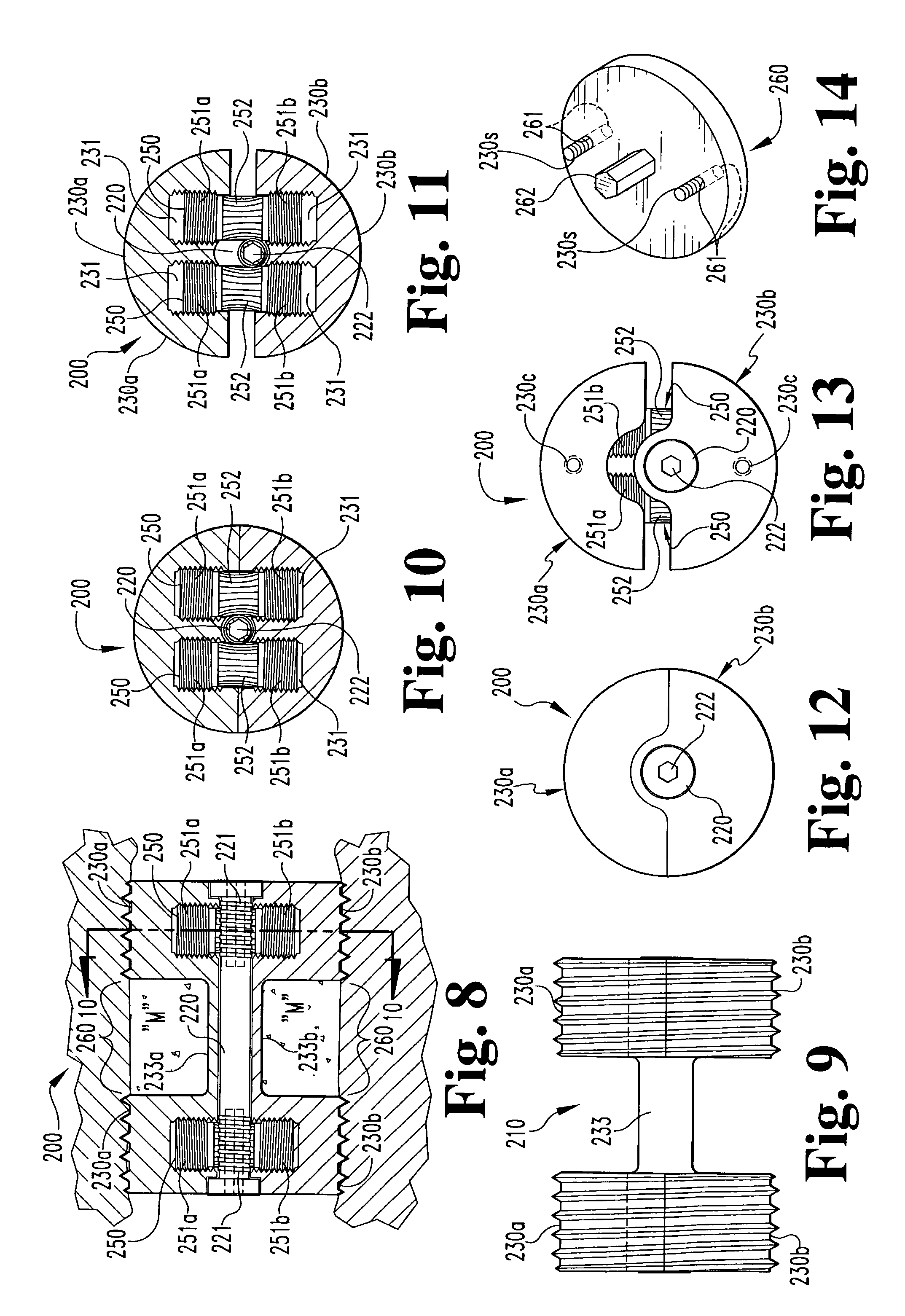
[0061]In accordance with a third embodiment, referring to FIGS. 15–18, an expandable osteogenic fusion implant 300 includes a rack-and-pinion type expansion member. implant 300 includes upper end 330a and lower end 330b, having corresponding bores 331. Elongate central portions 333a and 333b extend between and connect the respective upper end portions 330a and the lower end portions 330b. Alternatively, only one elongate central member 333 may be included extending between either the upper end portions 330a or the lower end portions 330b. In either case, the elongate central member may be permanently or removably attached to the end portions 330a and / or 330b, such as by welding, screwing or bolting. Alternatively, the end portions 330a and 330b and the elongate member 333 may be formed as one piece. The implant 300 further includes gear racks 350, having rack teeth 351, disposed within each bore 331. The implant 300 also includes central axle 320 having central axle gear teeth 321 c...


PUM


Abstract

An intervertebral disc space implant includes spaced-apart bone engagement portions that define an intermediate chamber that holds bone growth inducing material into contact with adjacent vertebral bodies. The implant is expandable to establish and maintain desired intervertebral spacing during fusion. The implant includes a first member and a second member arranged to move relative to each other by action of an expansion member, the first member being engageable with the vertebral body below the disc space.

Description

BACKGROUND OF THE INVENTION[0001]The present invention relates to an implant device to be placed into a portion of the intervertebral space between adjacent vertebrae. Specifically, the invention concerns an expandable osteogenic fusion device that may enhance arthrodesis or fusion between adjacent vertebral bodies while also maintaining the height of the intervertebral space at the instrumented vertebral level.[0002]In many cases, low back pain originates from damages or defects in a spinal disc between adjacent vertebral bodies. The disc can be herniated or can be affected by a variety of degenerative conditions. Frequently, pathologies affecting the spinal disc can disrupt the normal anatomical function of the disc. In some cases, this disruption is significant enough that surgical intervention is indicated.[0003]In one such surgical treatment, the affected disc is essentially removed and the adjacent vertebral bodies are fused together. In this treatment, a discectomy procedure ...

Claims


Application Information

Patent Timeline
Patent Type & Authority Patents(United States)
IPC IPC(8): A61F2/44A61F2/00A61F2/02A61F2/28A61F2/30A61F2/46
CPCA61F2/4455A61F2/28A61F2310/00293A61F2/446A61F2/447A61F2/4611A61F2002/2817A61F2002/2835A61F2002/30069A61F2002/30092A61F2002/30113A61F2002/30153A61F2002/30225A61F2002/30233A61F2002/30265A61F2002/30364A61F2002/3038A61F2002/30392A61F2002/30393A61F2002/30411A61F2002/30433A61F2002/30451A61F2002/30462A61F2002/30476A61F2002/3052A61F2002/30523A61F2002/30525A61F2002/3055A61F2002/30556A61F2002/30563A61F2002/30566A61F2002/30571A61F2002/30579A61F2002/30616A61F2002/30772A61F2002/30841A61F2002/3085A61F2002/30975A61F2002/4475A61F2210/0014A61F2220/0025A61F2220/0033A61F2220/0041A61F2220/0058A61F2220/0075A61F2230/0006A61F2230/0019A61F2230/0069A61F2230/0082A61F2250/0009A61F2/442A61F2002/30331A61F2002/30593
Inventor MCKAY, WILLIAM F.
Owner WARSAW ORTHOPEDIC INC
Why Eureka
Try Eureka