Transfer chamber for vacuum processing system

a vacuum processing system and transfer chamber technology, applied in the field of transfer chambers, can solve the problems of increased manufacturing difficulty, increased weight, and vacuum-induced stress on components, and achieve the effect of saving cost and weight and greater strength

Inactive Publication Date: 2006-03-28
APPLIED MATERIALS INC
View PDF14 Cites 38 Cited by
  • Summary
  • Abstract
  • Description
  • Claims
  • Application Information

AI Technical Summary

Benefits of technology

[0013]Because the transfer chamber bottom provided in accordance with the invention has a domed configuration, the inventive transfer chamber bottom exhibits greater strength than would a transfer chamber bottom of equal thickness having a flat configuration. Accordingly, the inventive transfer chamber bottom may be made thinner than conventional flat bottoms of transfer chambers of comparable size, thereby providing savings in cost and weight.

Problems solved by technology

However, increasing the size of a transfer chamber increases vacuum induced stresses in components thereof such as the bottom of the transfer chamber.
However, increased thickness of the transfer chamber bottom results in greater weight, increased difficulty in manufacture, and higher cost.

Method used


Image

  • Transfer chamber for vacuum processing system
  • Transfer chamber for vacuum processing system
  • Transfer chamber for vacuum processing system

Examples


Embodiment Construction

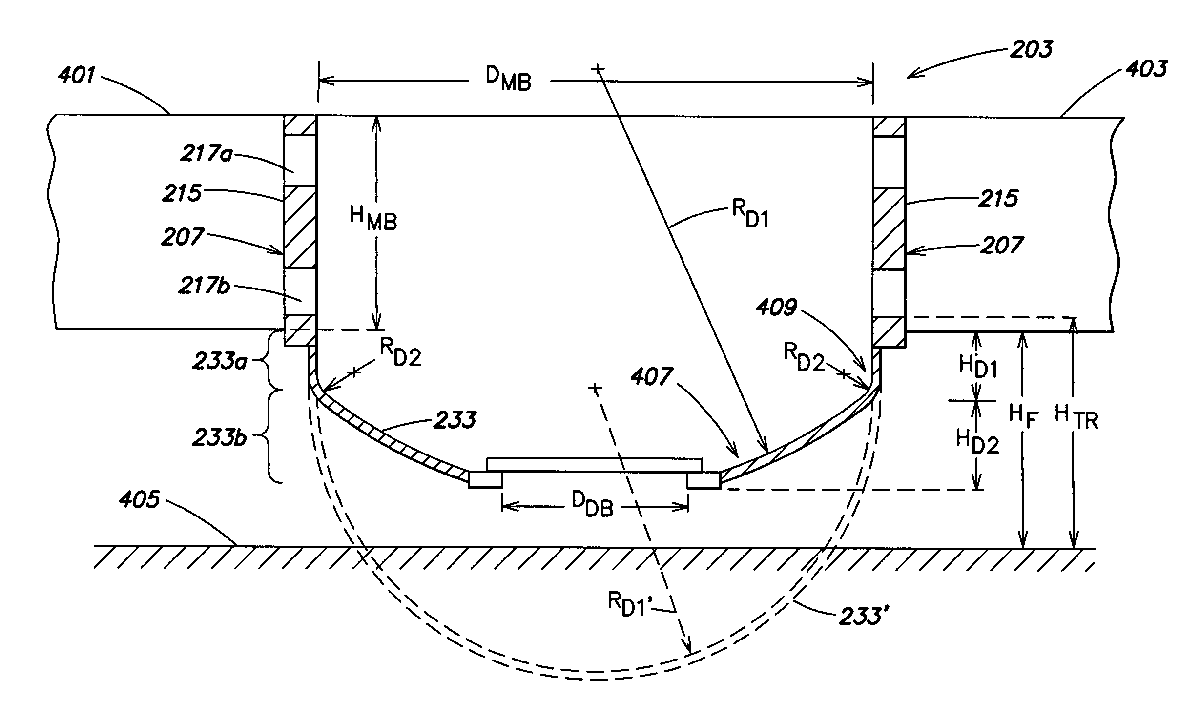
[0020]In accordance with the invention, the bottom of a transfer chamber is provided in a domed configuration, thereby achieving greater strength for a given thickness of the bottom and reducing the interior volume of the transfer chamber. As a result, the bottom of the transfer chamber may be made thinner than conventional transfer chamber bottoms, so that a savings in cost and weight is realized. The reduced interior volume of the transfer chamber also may decrease pump down times, thereby increasing throughput.

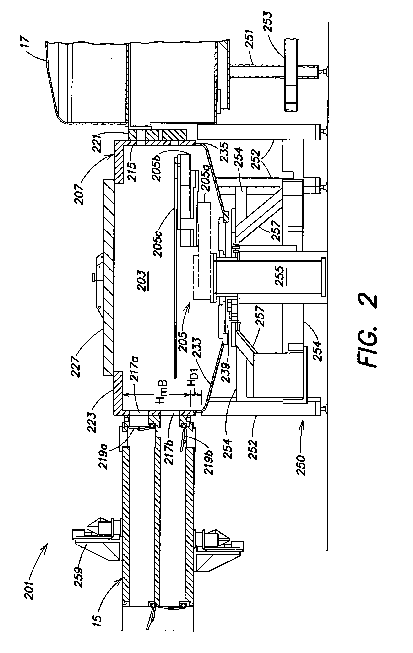
[0021]An embodiment of the invention will now be described with reference to FIGS. 2 and 3.

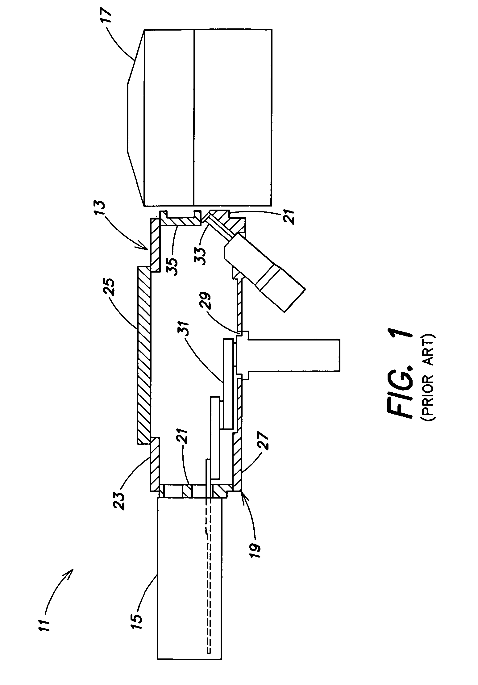
[0022]FIG. 2 is a view similar to FIG. 1 of a processing tool (vacuum processing system) 201 provided in accordance with an embodiment of the present invention. The inventive processing tool 201 includes a novel transfer chamber 203. A conventional load lock chamber 15 (which may be, for example, a double dual slot load lock (DDSL) or other conventional load lock) and a conventional p...


PUM

PropertyMeasurementUnit
thicknessaaaaaaaaaa
thicknessaaaaaaaaaa
thicknessaaaaaaaaaa

Abstract

A transfer chamber for a substrate processing tool includes a main body having side walls adapted to couple to at least one processing chamber and at least one load lock chamber. The main body houses at least a portion of a robot adapted to transport a substrate between the processing chamber and the load lock chamber. A lid couples to and seals a top of the main body of the transfer chamber. The transfer chamber also has a domed bottom adapted to couple to and to seal a bottom portion of the main body of the transfer chamber.

Description

[0001]The present application claims priority from U.S. Provisional Patent Application Ser. No. 60 / 390,629, filed Jun. 21, 2002, and titled “Transfer Chamber For Vacuum Processing System” and from U.S. Provisional Patent Application Ser. No. 60 / 392,578, filed Jun. 28, 2002, and titled “Transfer Chamber For Vacuum Processing System”, both of which are hereby incorporated by reference herein in their entirety.FIELD OF THE INVENTION[0002]This invention is generally concerned with processing systems used for processing substrates, and is more particularly concerned with a transfer chamber for use in such a system.BACKGROUND OF THE INVENTION[0003]Conventional techniques for manufacturing flat panel displays or semiconductor devices entail applying a sequence of processes to a substrate such as a glass plate or a silicon wafer. The processes to be applied may include thermal processing, physical vapor deposition (PVD), chemical vapor deposition (CVD), etching, etc. Typically, each process...

Claims


Application Information

Patent Timeline
Patent Type & Authority Patents(United States)
IPC IPC(8): C23C14/34C23C16/00C23C14/56C23C16/54H01L21/00H01L21/02H01L21/205H01L21/677
CPCC23C14/566C23C16/54H01L21/67126H01L21/67739H01L21/67748H01L21/67196Y10S414/135H01L21/02H01L21/68
Inventor KURITA, SHINICHIBEER, EMANUELNGUYEN, HUNG T.BLONIGAN, WENDELL T.
Owner APPLIED MATERIALS INC
Why Eureka
Try Eureka