Method and apparatus for erosion machining with an electrical contact element

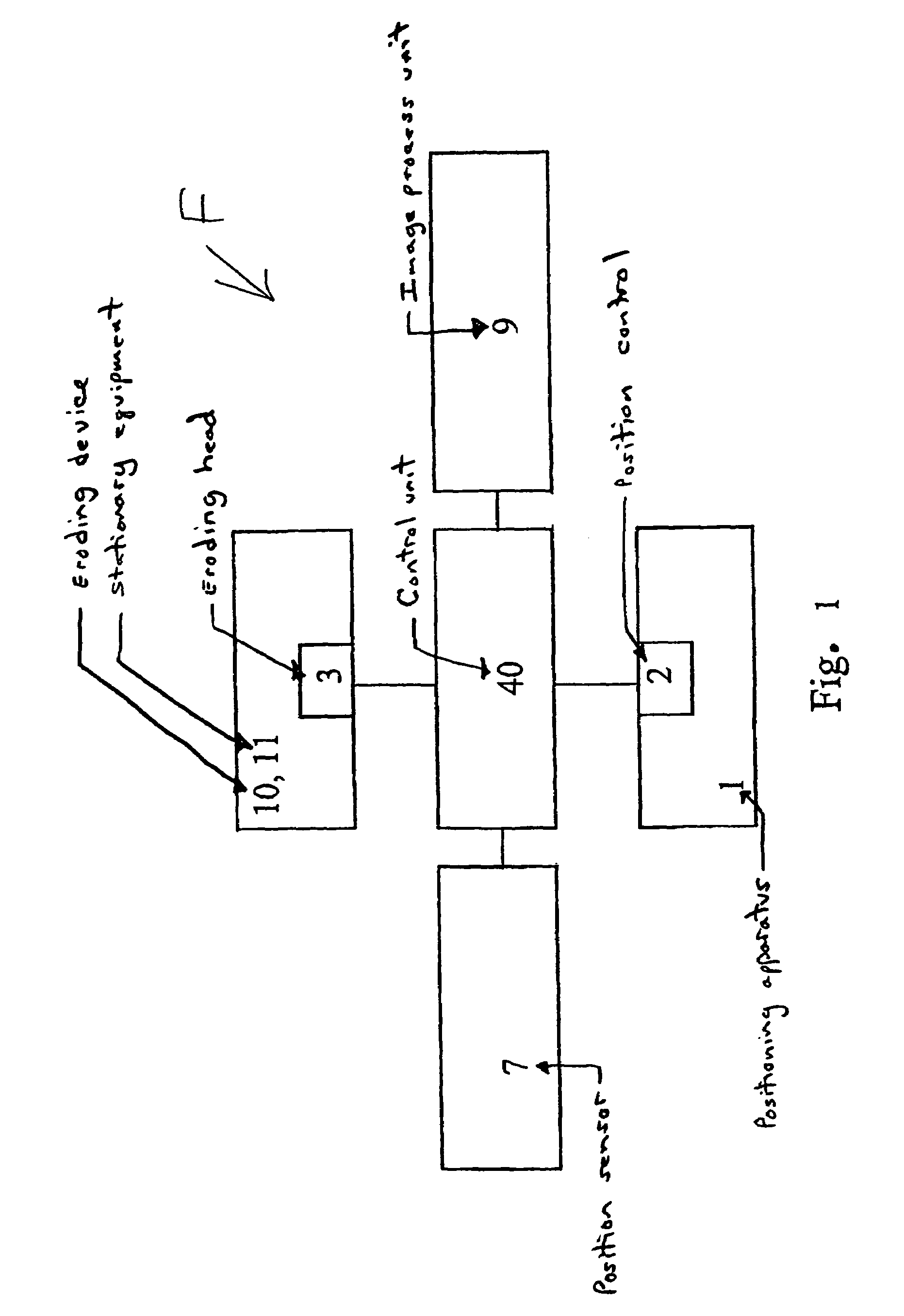
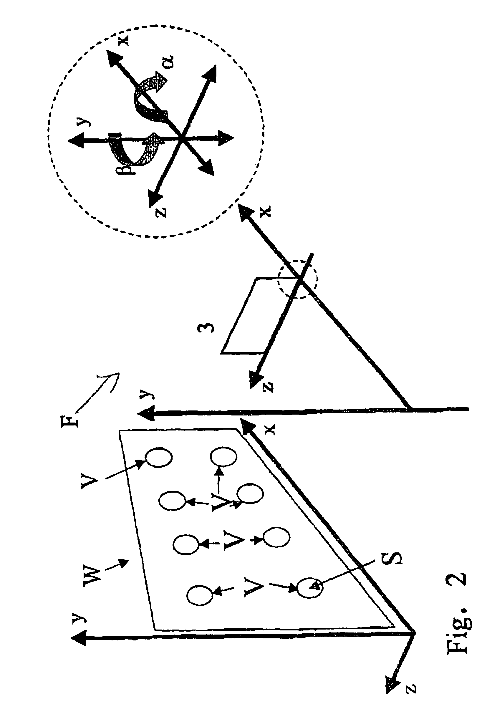
a technology of contact element and erosion machining, which is applied in the direction of resistance welding apparatus, electrical-based machining apparatus, electrode vibration holders, etc., can solve the problems of damage to structural parts that are held together by connecting elements, prior methods are not usable on components or structural components whose, and material in the vicinity of erosion processes is impaired

Active Publication Date: 2006-03-28
AIRBUS DEFENCE & SPACE
View PDF7 Cites 8 Cited by
  • Summary
  • Abstract
  • Description
  • Claims
  • Application Information

AI Technical Summary

Benefits of technology

[0009]The invention provides for an erosion apparatus for the shaping machining of a metallic structural component or a metallic insert element in a non-metallic structural component, in particular, for the removing of metallic connecting elements, as well as a method for the eroding of such components or elements, with which a removal of connecting elements from structural parts is possible, and as economical as possible, and that can be used on the greatest possible number of materials for the structural parts.
[0011]One advantage of the erosion apparatus according to the invention with the grounding device, or of the method according to the invention, is that with either of these, a reduction of process times as well as a reduction in tool wear can be achieved due to an improvement of the current flow. Through the solution according to the invention, the process parameters can be ascertained and monitored better. Moreover, the spatial limitation of the current flow enables the resulting electrical field to be made more compact, so that the interference behavior of the erosion apparatus internally and externally is reduced.
[0012]The solution according to the invention with the grounding device can be used without a flushing cage on metallic structural components that are immersed in a dielectric bath. The solution according to the invention enables, e.g., the introduction of exact bores or chips without the material structure in the vicinity being changed.
[0013]The use of a flushing cage is to be provided during the machining of metallic structural components and of metallic insert elements such as, e.g., connecting elements or insert elements such as insert sleeves, in non-metallic structural components. The solution according to the invention with the grounding device enables the targeted machining of the connecting elements for a great variety of applications. The solution according to the invention with the grounding device is particularly advantageous in the machining of metallic connecting elements that are inserted into likewise metallic structural components with non-metallic sealing arrangements such as, e.g., sealing rings or sealing compounds, for the purposes of insulation or sealing.
[0024]The apparatus may further comprise a rotary drive structured and arranged rotate the electrode during erosion machining. The apparatus may further comprise a flushing cage structured and arranged to allow burned-off particles to be transported away from the flushing cage via a vacuum suction acting in an interior of the flushing cage. The apparatus may further comprise at least one of a position sensor and at least one camera module for a pre-positioning of the eroding head. The apparatus may further comprise at least two camera modules, one camera module being arranged to identify a plurality of connecting elements for rough orientation and pre-positioning of the eroding head with respect to a workpiece, and another camera module being arranged to optically identify an individual connecting element for an image processing system and for a fine positioning of the eroding head, whereby the image processing system determines at least one of a center point and coordinates of the individual connecting element.
[0027]The method may further comprise during a pre-positioning, at least one of using two camera modules to position the electrode in a desired location, wherein one camera module is utilized to identify a plurality of connecting elements for rough orientation and pre-positioning of the erosion head with respect to the structural component, and another camera module is utilized to optically identify an individual connecting element for an image processing system and for a fine positioning of the erosion head, whereby the image processing system determines at least one of a center point of the individual connecting element and coordinates of the individual connecting element.

Problems solved by technology

In these methods, the material in the vicinity of the erosion processes is impaired.
For this reason prior methods are not usable on components or structural components whose material properties can be changed in an inadmissible manner by the erosion process.
A disadvantage of this drilling process is that structural parts that are held together by the connecting elements may be damaged.
Thus a very hard material is present precisely in the center of the rivet, so that when connecting elements are removed according to the prior art, the following further problems result: the quality of the centering, i.e., the precision with which the power drill is applied, depends on the manual dexterity of the craftsman, resulting however in a scatter with relatively imprecise centerings.
Moreover, the tool, i.e., the drill, wears particularly severely at draw rivets as a function of the pressing pressure exerted.
Another disadvantage is a possible heat development that occurs, in particular, when the cutting action of the drill decreases sharply due to wear, or the rivet turns together with the tool, which causes increased frictional heat and through which damage to the structure (structural change) can occur.
For these reasons this drilling process is only suitable to a limited extent for the removing of connection rivets with drawing mandrels.

Method used


Image

  • Method and apparatus for erosion machining with an electrical contact element
  • Method and apparatus for erosion machining with an electrical contact element
  • Method and apparatus for erosion machining with an electrical contact element

Examples


Embodiment Construction

[0039]The particulars shown herein are by way of example and for purposes of illustrative discussion of the embodiments of the present invention only and are presented in the cause of providing what is believed to be the most useful and readily understood description of the principles and conceptual aspects of the present invention. In this regard, no attempt is made to show structural details of the present invention in more detail than is necessary for the fundamental understanding of the present invention, the description taken with the drawings making apparent to those skilled in the art how the several forms of the present invention may be embodied in practice.

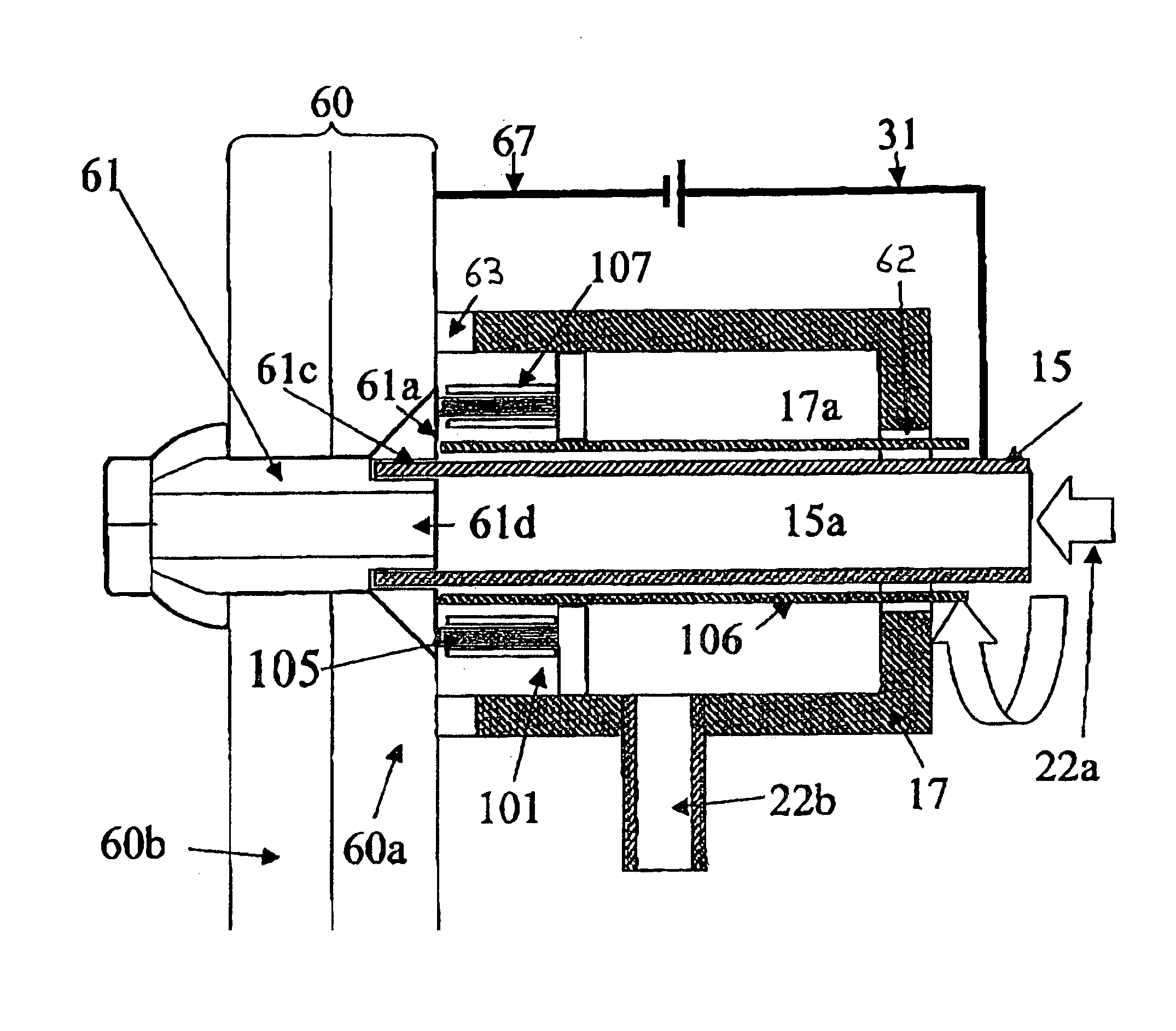
[0040]An erosion apparatus according to the invention using a corresponding flushing cage is described below, which apparatus is provided for the application case of a shaping machining of a metallic structural component or of a metallic insert element in a non-metallic structural component, in particular, for the removal...


PUM

PropertyMeasurementUnit
conductivityaaaaaaaaaa
temperaturesaaaaaaaaaa

Abstract

Apparatus and method for erosion machining a structure comprising one of a metallic structural component, a metallic insert element, and a connecting element, by way of erosion. The apparatus includes an eroding head including an electrode, a power supply, and a control device. The power supply and the control device produce an erosion current. A grounding device is arranged in an area of the eroding head and includes at least one contact element. When the eroding head is arranged to perform erosion machining, the at least one contact element contacts and forms an electrical connection with a surface of the structure, whereby an eroding electric circuit is formed via the electrode and the structure. The method includes arranging the erosion head in an area of the connecting element, sealing, with a seal, a flushing cage to the structural component, contacting a portion the connecting element with the electrode; and electrically connecting the at least one contact element and another portion of the connecting element. This Abstract is not intended to define the invention disclosed in the specification, nor intended to limit the scope of the invention in any way.

Description

CROSS-REFERENCE TO RELATED APPLICATIONS[0001]The present application claims priority under 35 U.S.C. §119 of German Patent Application No. 103 56 394.6, filed on Dec. 3, 2003, the disclosure of which is expressly incorporated by reference herein in its entirety.BACKGROUND OF THE INVENTION[0002]1. Field of the Invention[0003]The invention relates to an erosion apparatus for the shaping machining of a metallic structural component or insert element as well as a method for the eroding of such elements or components with an erosion apparatus. This machining can include the machining of a metallic structural component or can include the machining of a metallic insert element in a non-metallic structural component or the machining of a metallic insert element placed in an insulated manner in a metallic structural component. In the two latter alternatives, the removal of metallic connecting elements from structural components is concerned in particular.[0004]2. Discussion of Background Inf...

Claims


Application Information

Patent Timeline
Patent Type & Authority Patents(United States)
IPC IPC(8): B23H1/00B23H9/00B23H7/20B23H11/00
CPCB23H7/20B23H11/006B23H9/001B23H9/00B21J15/50
Inventor BERMANN, JOHANNMEISTER, TITUS
Owner AIRBUS DEFENCE & SPACE
Why Eureka
Try Eureka