Method of applying a tube member in a stator slot in a rotating electrical machine

a technology of rotating electrical machines and tube members, which is applied in the direction of windings, dynamo-electric components, cooling/ventilation arrangements, etc., can solve the problems of large ventilation loss, mechanical weakening of ventilation ducts, and long stators, so as to eliminate short-circuit risk, increase density, and high density

Inactive Publication Date: 2006-03-28
ABB (SCHWEIZ) AG
View PDF756 Cites 19 Cited by
  • Summary
  • Abstract
  • Description
  • Claims
  • Application Information

AI Technical Summary

Benefits of technology

[0027]Polymer cooling tubes are non-conducting and the risk of short-circuiting is therefore eliminated, nor can eddy currents occur in them. Polymer cooling tubes can also be bent cold and drawn through several cooling tube channels without splicing, which is a great advantage.
[0028]Polymer cooling tubes can be produced from many materials, such as polyethylene, polypropene, polybutene, polyvinylidene fluoride, polytetrafluoroethylene, as well as filled and reinforced elastomers. Of these materials, polyethylene with high density, HDPE, is preferred since its thermal conductivity increases with increased density. If the polyethylene is cross-linked, which can be achieved by splitting a peroxide, silane cross-linking or radiation patterning, its ability to withstand pressure at increased temperature is enhanced, at the same time as the risk of voltage corrosion disappears. Cross-linked polyethylene, e.g. XLPE tubing from Wirsbo bruks AB, is used, for instance, for water pipes.

Problems solved by technology

The drawback with air-cooling is that the ventilation losses are considerable and that, because of the ventilation ducts, the stator becomes longer.
Furthermore, particularly with said high-voltage generators with long teeth, the ventilation ducts may also weaken the structure mechanically.
One drawback is that eddy currents are induced in metal tubes if they are present in a magnetic flux varying with time, thus leading to certain power losses when used in an electric machine.

Method used


Image

  • Method of applying a tube member in a stator slot in a rotating electrical machine
  • Method of applying a tube member in a stator slot in a rotating electrical machine
  • Method of applying a tube member in a stator slot in a rotating electrical machine

Examples


Embodiment Construction

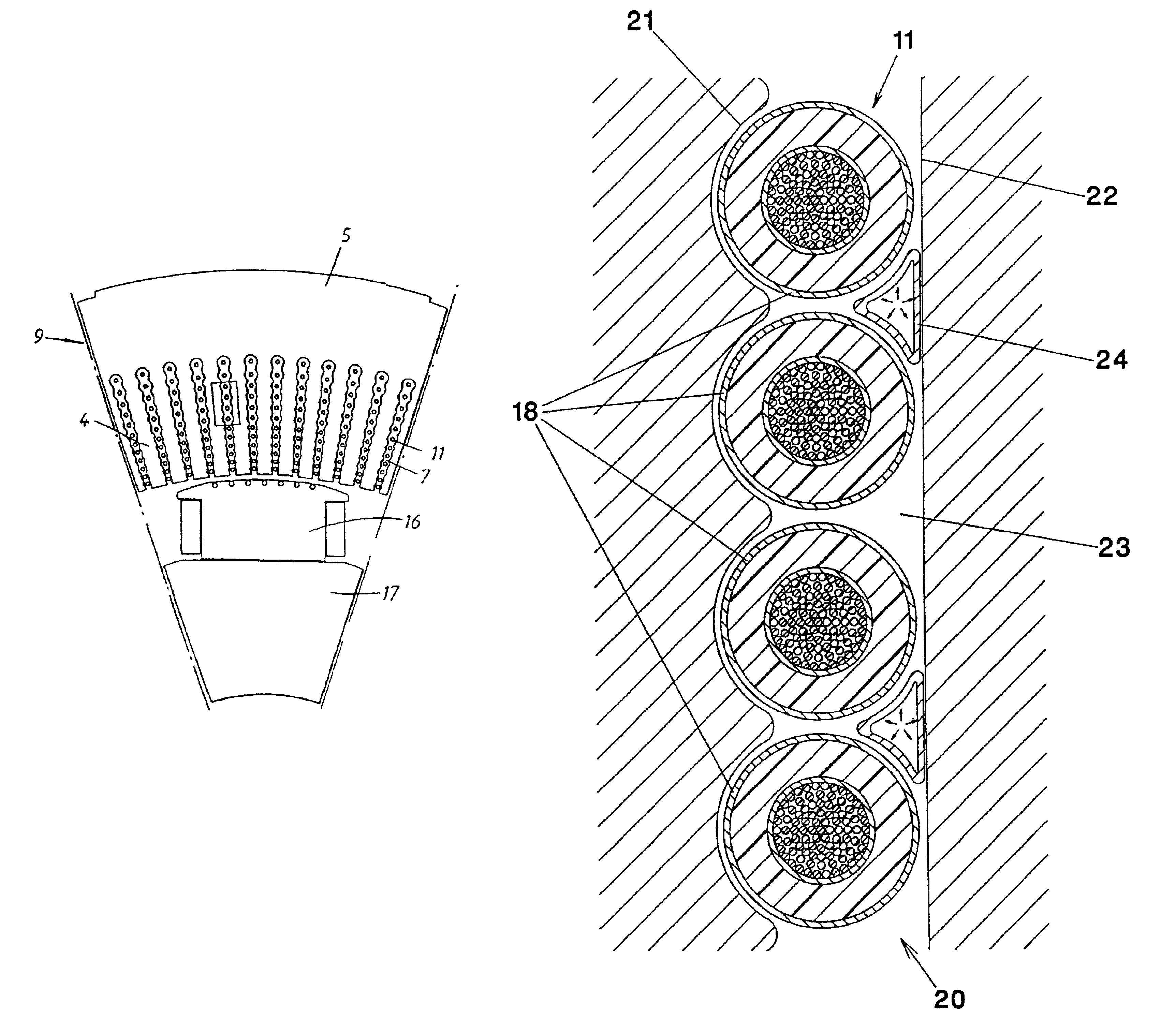
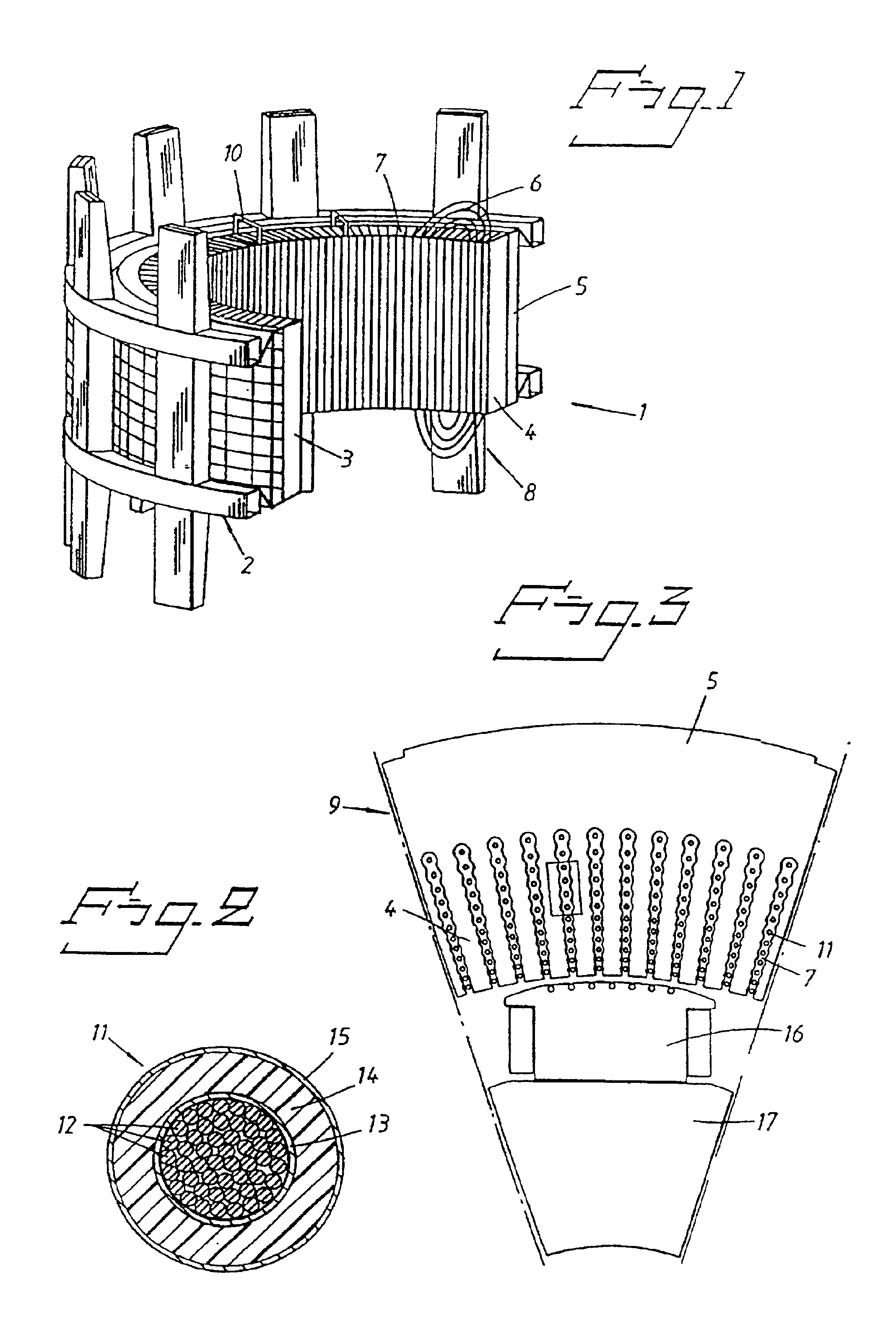
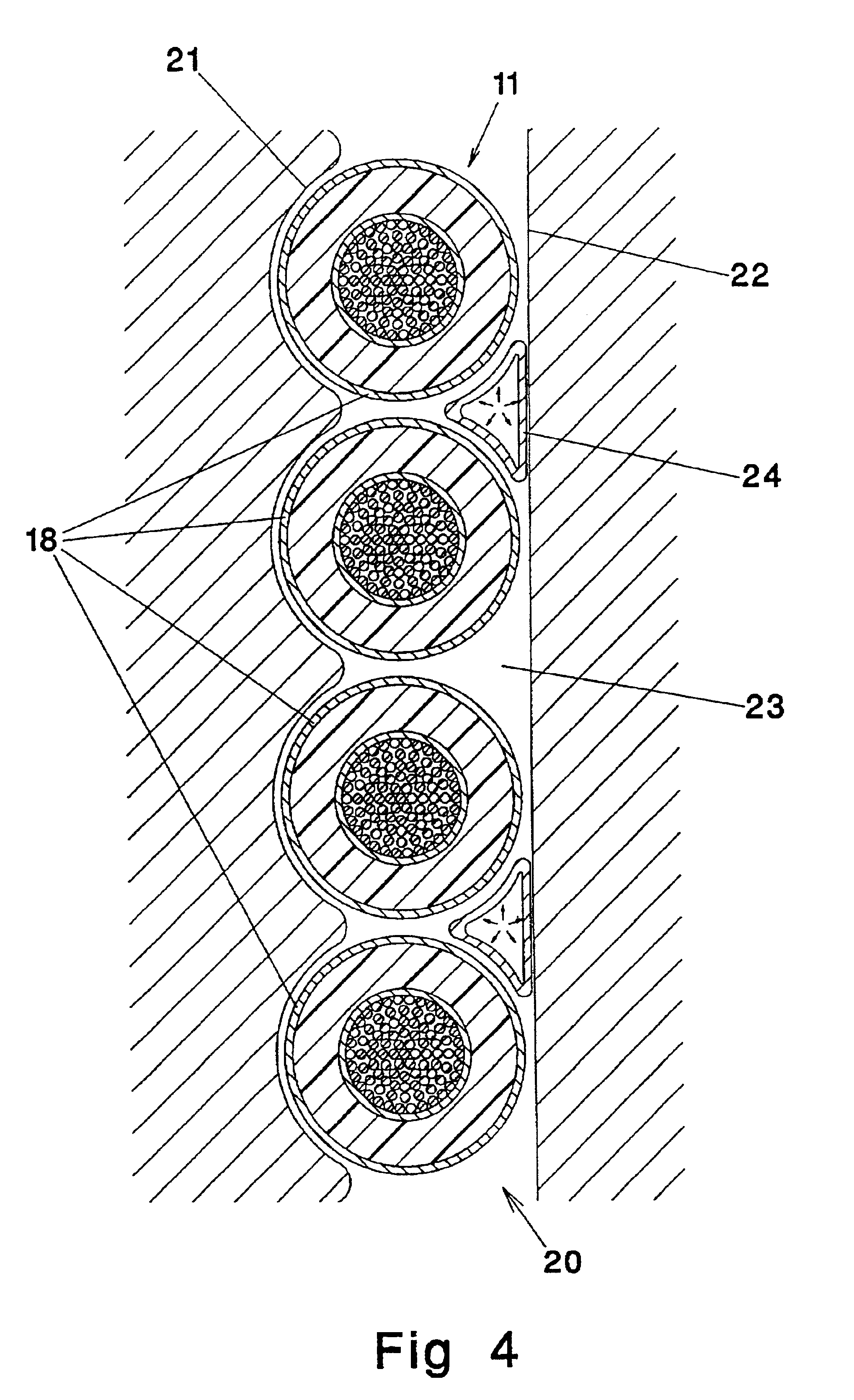
[0046]FIG. 1 shows part of an electric machine in which the rotor has been removed to reveal more clearly how a stator 1 is arranged. The main parts of the stator 1 include a stator frame 2, a stator core 3 having stator teeth 4 and a stator yoke 5. The stator also has a stator winding 6 in the form of a high-voltage cable, placed in a space 7 shaped like a bicycle chain, see FIG. 3, formed between each individual stator tooth 4. In FIG. 3 the stator winding 6 is only indicated by its electric conductors. As shown in FIG. 1, the stator winding 6 forms a coil-end bundle 8 on each side of the stator 1. FIG. 3 also reveals that the insulation of the high-voltage cable is stepped in several dimensions depending on its radial location in the stator 1. For the sake of simplicity only one coil-end bundle is shown in FIG. 1 at each end of the stator.

[0047]In large conventional machines the stator frame 2 often has a welded steel plate construction. In large machines the stator core 3, also ...


PUM


Abstract

A method for mounting a tube in a space having a shape corresponding to the shape of the tube. The tube is inserted into the space, pressurized with a hot pressure medium causing the tube to expand until the space is filled, then a cold pressure medium is substituted for the hot pressure medium while maintaining constant pressure causing the tube to solidify in its expanded shape. Also, a rotating electric machine having such a tube between windings of a high-voltage cable in a stator slot.

Description

BACKGROUND OF THE INVENTION[0001]1. Field of the Invention[0002]The present invention relates to rotating electric machines such as synchronous machines. It also relates to double-fed machines, applications in asynchronous static current converter cascades, external pole machines and synchronous flux machines, as well as to alternating current machines intended primarily as generators in a power station for generating electric power. The invention particularly relates to the stator in such machines and a method for fixing the windings, as well as cooling the stator teeth and the insulated electric conductor constituting the stator winding.[0003]2. Discussion of the Background[0004]Similar machines have conventionally been designed for voltages in the range 15-30 kV, and 30 kV has normally been considered to be an upper limit. This generally means that a generator must be connected to the power network via a transformer which steps up the voltage to the level of the power network, wh...

Claims


Application Information

Patent Timeline
Patent Type & Authority Patents(United States)
IPC IPC(8): H02K3/24H02KH02K3/40H02K3/48
CPCH02K3/48H02K3/40Y10S174/32H02K2203/15H02K3/24
Inventor LARSSON, BERTILROTHMAN, BENGT
Owner ABB (SCHWEIZ) AG
Why Eureka
Try Eureka