Non-destructive determination of machining induced surface defects on metal parts

a technology of machining induced defects and metal parts, which is applied in the direction of mechanical measurement arrangements, mechanical roughness/irregularity measurements, instruments, etc., can solve the problems of reducing the life of low cycle fatigue (lcf), and affecting the quality of machining

Inactive Publication Date: 2006-03-28
GENERAL ELECTRIC CO
View PDF9 Cites 18 Cited by
  • Summary
  • Abstract
  • Description
  • Claims
  • Application Information

AI Technical Summary

Benefits of technology

[0005]In one aspect, a non-destructive method of detecting and measuring machining induced surface defects on gas turbine engine components is provided. The method includes positioning an evanescent microwave microscope probe adjacent a turbine component surface, and scanning the turbine component surface by moving at least one of the evanescent microwave microscope probe and the component surface in an x-y plane while maintaining a predetermined distance between the probe and the component surface constant.
[0006]In another aspect, a non-destructive method of detecting and measuring machining induced surface defects on gas

Problems solved by technology

Machining process, for example, broaching on gas turbine engine components can produce a surface damaged metallurgical layer.
This surface damaged layer can result in reduced low cycle fatigue (LCF) lives.
Machining of turbine components causes

Method used


Image

  • Non-destructive determination of machining induced surface defects on metal parts
  • Non-destructive determination of machining induced surface defects on metal parts
  • Non-destructive determination of machining induced surface defects on metal parts

Examples


Embodiment Construction

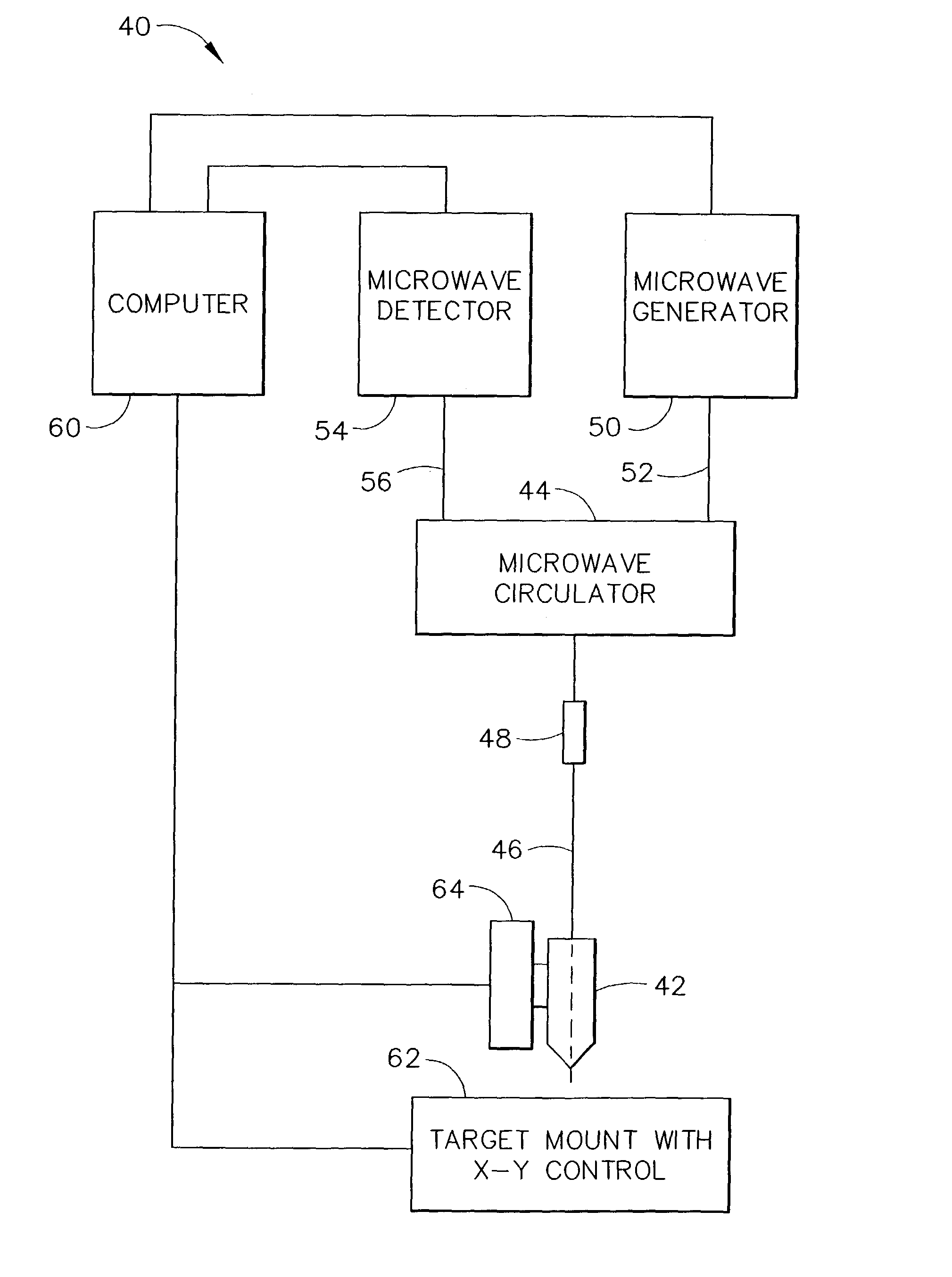
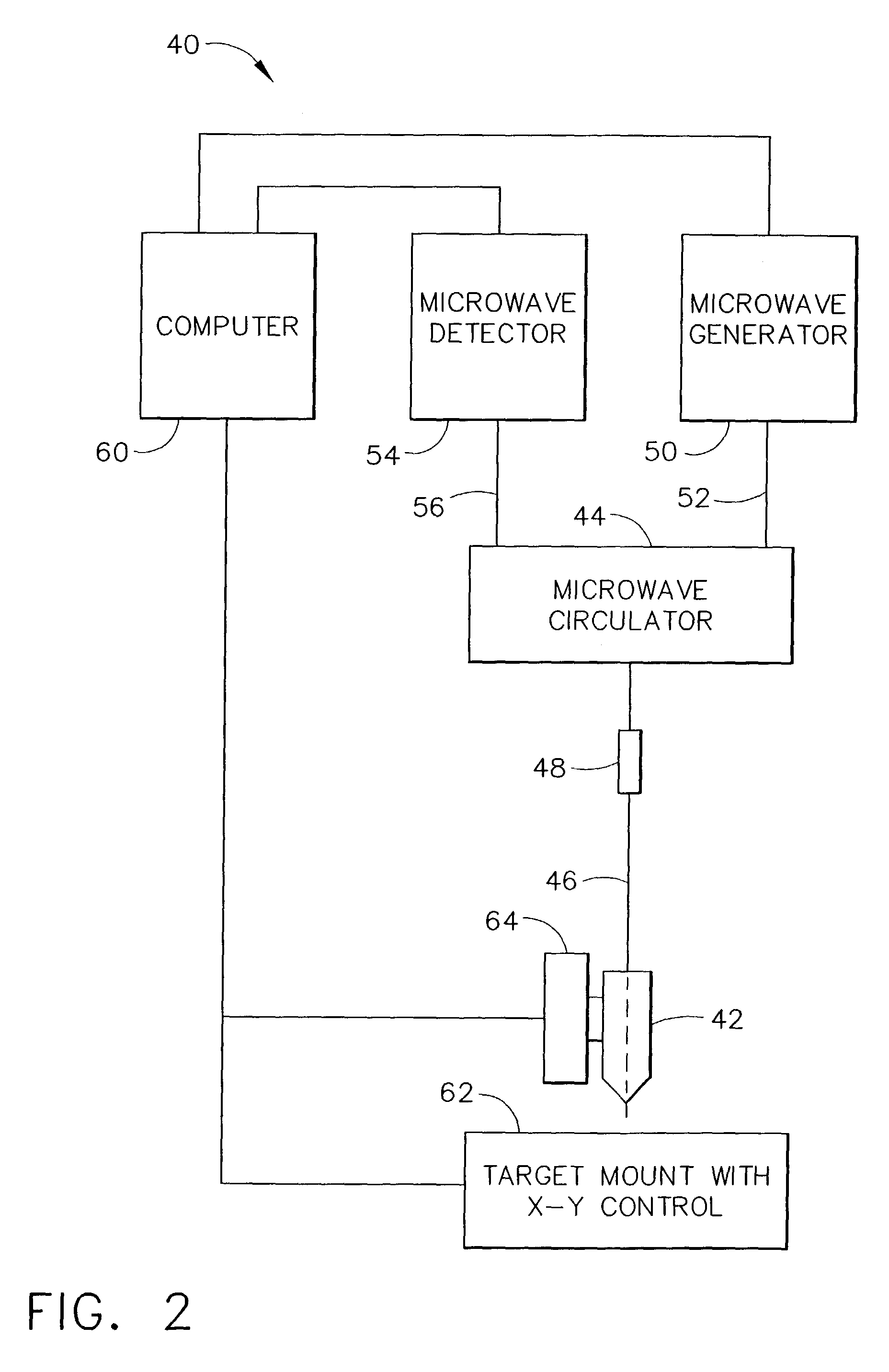
[0012]Non-destructive examination of machining induced surface defects on gas turbine engine components using evanescent microwave microscopy is described in detail below. Evanescent microwave microscopy is used for imaging scans of the surface of turbine components with resolutions of λ / 1000 or better, where λ is the wavelength of microwave energy in free space. Evanescent microwaves are capable of high resolution imaging using “near fields”. This permits non-destructive imaging of materials that are sensitive to near field microstructure. The evanescent microwave probe measures frequency as it traverses a surface. The frequency is sensitive to probe distance, conductivity, dielectric, and changes of the near surface material. The cold worked surface of a machined metal exhibits a change in conductivity due to a change in grain size or localized melting at the near surface.

[0013]In evanescent microwave field imaging, the fields are intentionally confined or restricted to regions th...


PUM


Abstract

A non-destructive method of detecting and measuring machining induced surface defects on gas turbine engine components is provided. In an exemplary embodiment, the method includes positioning an evanescent microwave microscope probe adjacent a turbine component surface, and scanning the turbine component surface by moving at least one of the evanescent microwave microscope probe and the component surface in an x-y plane while maintaining a predetermined distance between the probe and the component surface constant.

Description

BACKGROUND OF THE INVENTION[0001]This invention relates generally to non-destructive examinations of gas turbine engine components, and more particularly to non-destructive evaluations of machining induced surface defects on gas turbine engine components.[0002]A gas turbine engine includes a compressor for compressing air which channeled to a combustor and mixed with a fuel, wherein the mixture is ignited for generating hot combustion gases. The combustion gases are channeled to a turbine, which extracts energy from the combustion gases for powering the compressor, as well as producing useful work to propel an aircraft in flight or to power a load, such as an electrical generator. Increased efficiency in gas turbine engines is facilitated at least in part by an increase in the operating temperature of the combustor.[0003]Machining process, for example, broaching on gas turbine engine components can produce a surface damaged metallurgical layer. This surface damaged layer can result ...

Claims


Application Information

Patent Timeline
IPC IPC(8): G01R27/04G01B5/28G01N22/02G01Q30/02
CPCB82Y20/00G01Q60/22B82Y35/00F05D2230/90F05D2260/83F01D5/005
Inventor HAZEL, BRIAN THOMASDAROLIA, RAMGOPAL
Owner GENERAL ELECTRIC CO
Why Eureka
Try Eureka