Data transmission method, data transmission system, transmitter and receiver

a data transmission system and data transmission technology, applied in the field of data transmission methods, data transmission systems, transmitters and receivers, can solve problems such as difficulty in detecting the rate of error, hardware scale of the memory, and inability of the receiving side to reproduce the transmitted data correctly, so as to reduce the probability of detecting the ra

Inactive Publication Date: 2006-03-28
NTT DOCOMO INC
View PDF17 Cites 16 Cited by
  • Summary
  • Abstract
  • Description
  • Claims
  • Application Information

AI Technical Summary

Benefits of technology

[0016]Accordingly, an object of the present invention is, in the variable rate data transmission, to decrease the probability of detecting the rate mistakenly at the receiving side and to eliminate the need for providing buffer for temporarily storing the transmitted data at the transmitting side.

Problems solved by technology

In addition, in the method where the receiving side determines the rate by using the error-detecting code that is added to the transmitted data to indicate the transmission quality without sending any rate information, a decision error rate in determining the rate depends on a word length of the error-detecting code and doesn't decrease below a certain rate-decision error rate (namely, a probability of determining that no transmission error exists for an erroneous rate) even if the transmission error goes down.
On the other hand, in the case where the rate information is sent from the transmitting side to the receiving side, if an error occurs during transmission, an effective data length in the received frame cannot be judged and it becomes difficult for the receiving side to reproduce the transmitted data correctly even if no error occurs in the data part.
Such buffer memory becomes large in size in proportion to the number of the transmitted data bits of one frame, and when a huge amount of the transmitted data is sent, hardware scale of the memory presents a problem.
However, when this technology is applied in actual radio communication environments, a proper value of Δ for obtaining desired detection performance may differ for each final bit position (i.e. different number of the transmitted data bits in the frame) depending on a distribution tendency of bit transmission errors in the transmission path.
For this case, if a single value of Δ is used in common, the rate detection performance varies according to the final bit position; therefore there arises a problem in that average quality of the variable rate data transmission including the rate detection performance changes when a distribution of occurrence probability for transmission rates (final bit positions) varies.

Method used


Image

  • Data transmission method, data transmission system, transmitter and receiver
  • Data transmission method, data transmission system, transmitter and receiver
  • Data transmission method, data transmission system, transmitter and receiver

Examples


first embodiment

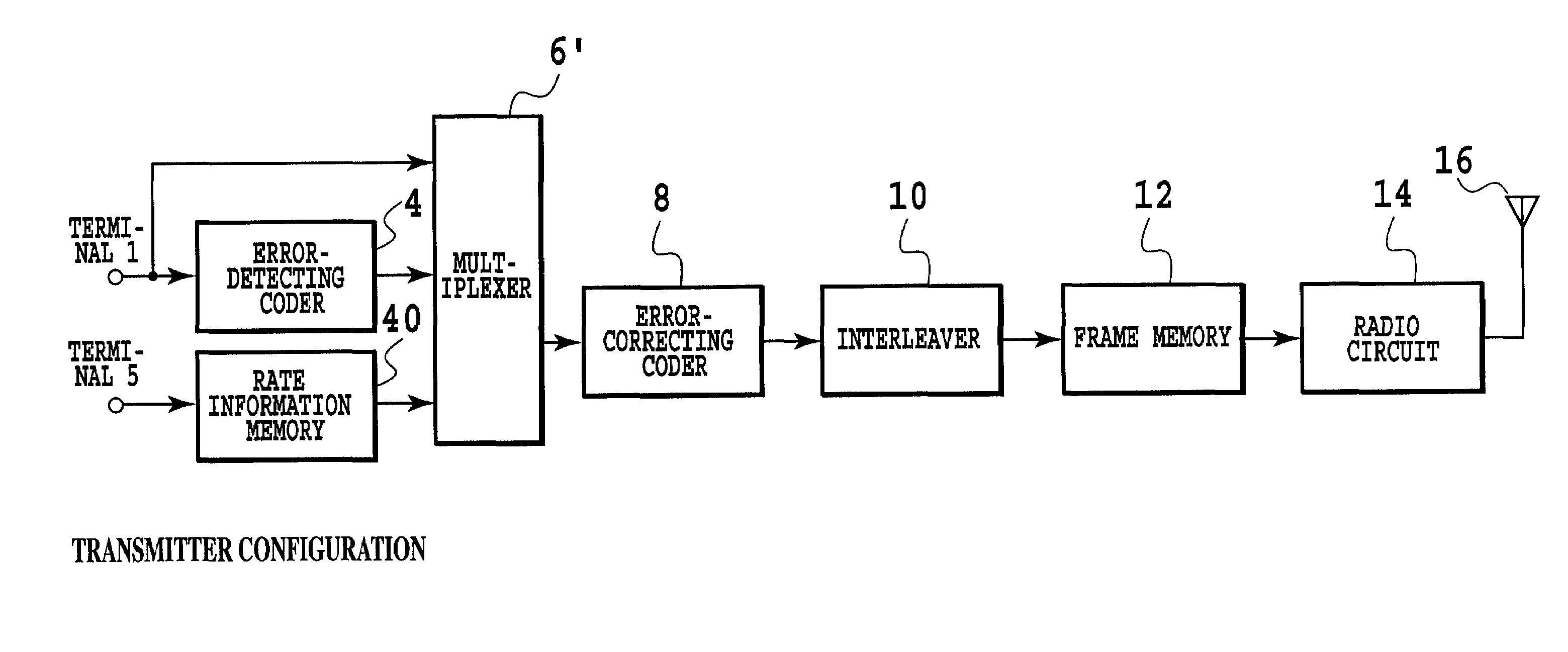
[0429]FIGS. 3A and 3B show examples of block constructs of a transmitter and a receiver in a first embodiment of the present invention.

[0430]In FIGS. 3A and 3B, a transmitted data sequence applied to a terminal 1 is sent both to an error-detecting coder 4 and to a multiplexer 6. The error-detecting coder 4 calculates the error-detecting code (in this embodiment, CRC parity bits (in short, CRC bits)) for one frame of the transmitted data. In this embodiment, the word length of the CRC bits is a fixed length.

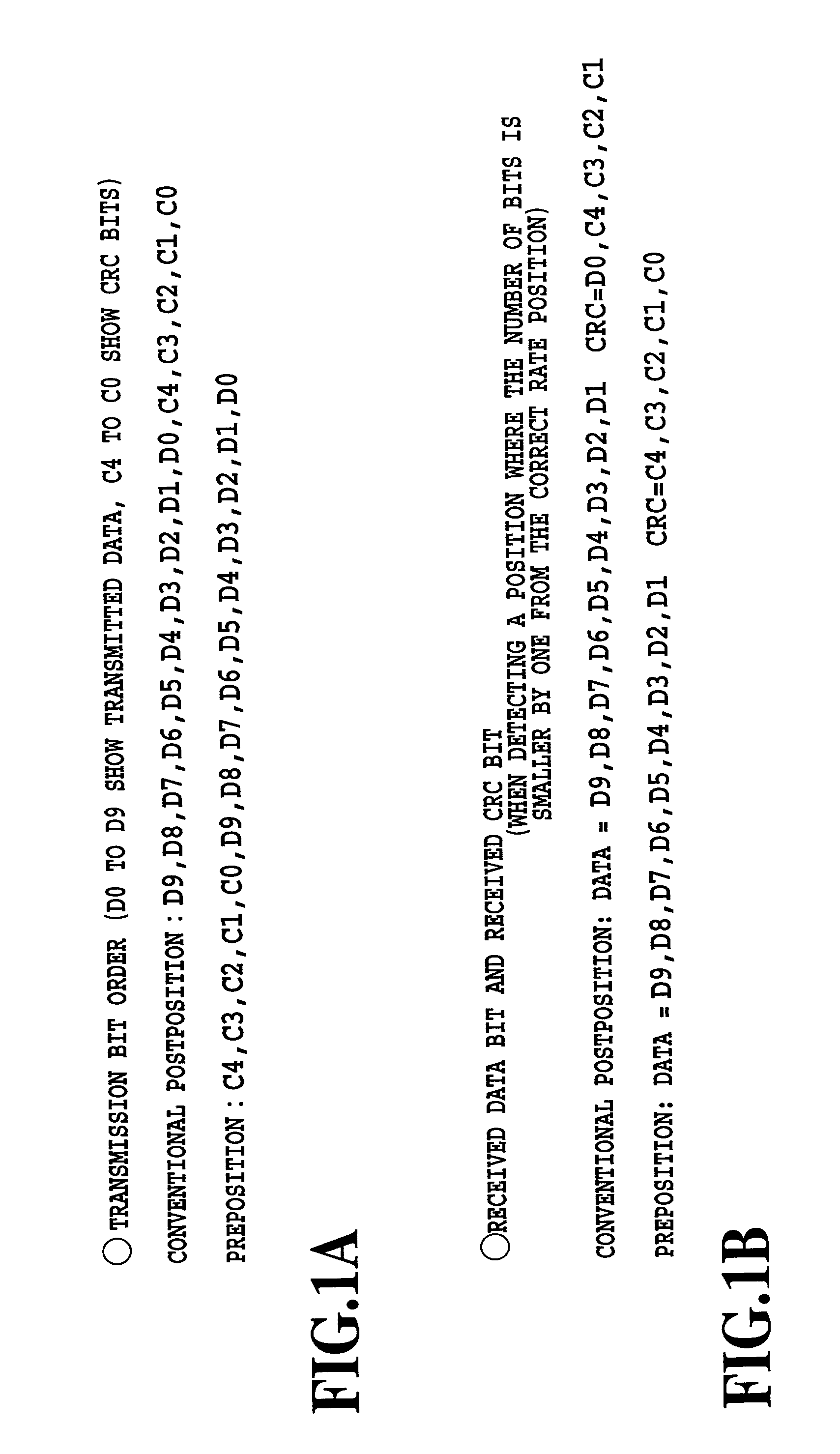
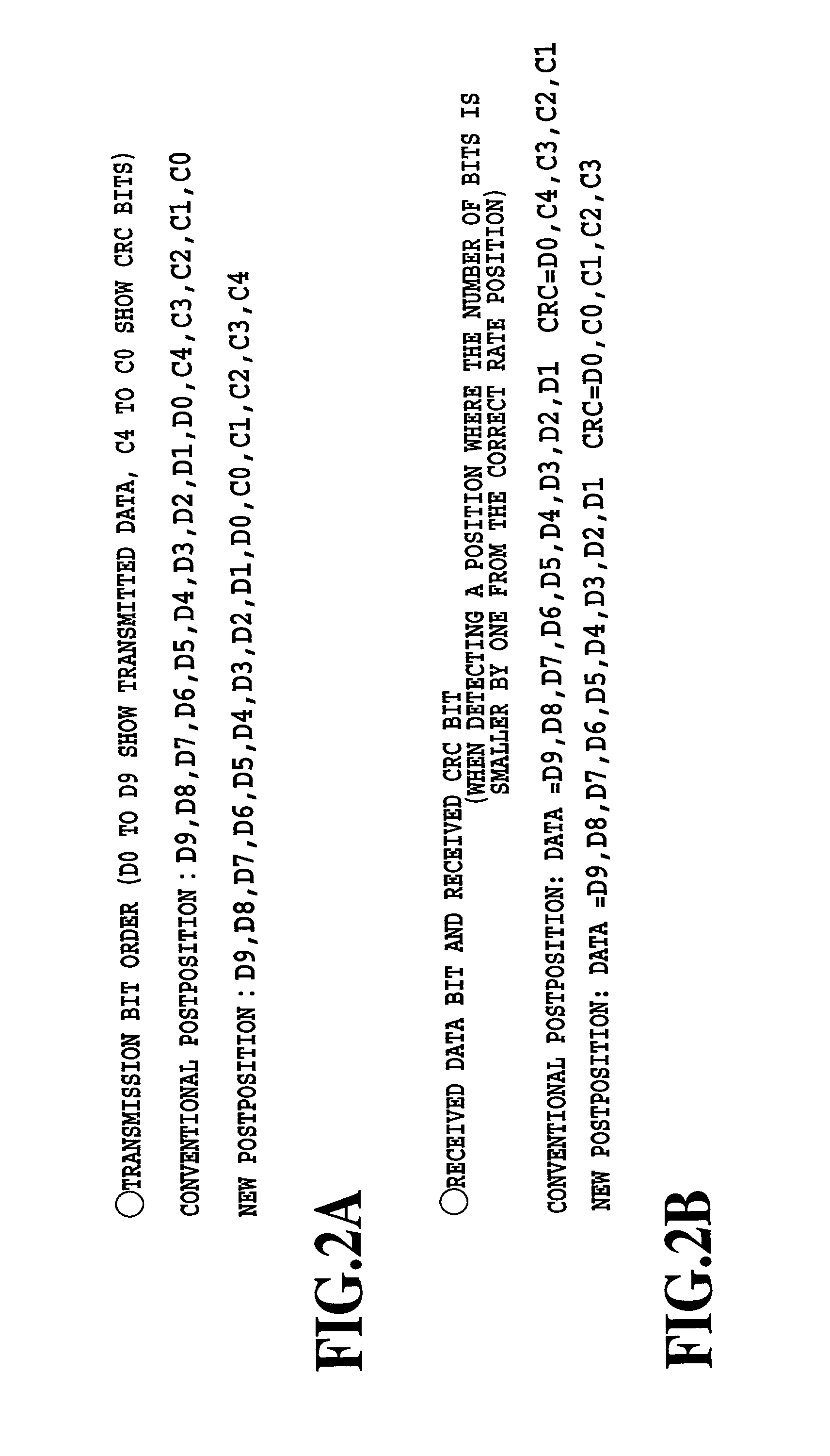
[0431]Next, the multiplexer 6 arranges the error-detecting code (the CRC bits) calculated by the error-detecting coder 4 after the transmitted data. Here, the bit arrangements of the transmitted data and of the error-detecting code are set in a reverse order to each other. Concretely, in this embodiment, the error-detecting coder 4 outputs the error-detecting code bits in a reverse order to the normal case.

[0432]By the way, in this embodiment, to conduct the error-correcting codin...

second embodiment

[0460]FIGS. 10A and 10B show examples of the block constructs of a transmitter and a receiver in a second embodiment according to the present invention.

[0461]In the configuration of FIGS. 10A and 10B, transmission of information indicating the rate of the transmitted data is added to the configuration of FIGS. 3A and 3B, and the receiving side uses this rate information additionally to make the rate decision. In FIGS. 10A and 10B, all the parts common to those of the configurations of FIGS. 3A and 3B are denoted by the same numerals. Description of operations will be given below, focusing on parts different from those of FIGS. 3A and 3B.

[0462]First, information indicating the rate of the transmitted data (transmission rate information) that is applied to the terminal 5 is sent to a rate information memory 40. Here, the contents of the rate information memory 40 are information indicating the rate information of the transmitted data, namely, the number of bits. A multiplexer 6′ outpu...

third embodiment

[0474]In the first embodiment and the second embodiment, it is possible that, considering a case where the number of bits of the transmitted data becomes zero, if the number of bits of the transmitted data is zero at the transmitting side, the frame data is generated by considering the previously-specified bit pattern to be the error-detecting code. It is possible that at the receiving side, a position where the number of bits of the transmitted data becomes zero is also assumed as the final bit position of the frame data (that is, in FIG. 13, a position where L=0 is also assumed as the final bit position of the frame data), and if the error-detecting code in the case of the the assumption agrees with the above-mentioned previously-specified bit pattern, a decision that the position where the number of bits of the transmitted data becomes zero is the final bit position of the frame data is made.

[0475]In actual data transmissions, there is a case where the number of bits of the trans...


PUM


Abstract

A data transmission method etc. are provided. At the transmitting side, an error-detecting code of the transmitted data is calculated, frame by frame, the error-detecting code is arranged after the corresponding transmitted data, and frame data is generated in such a way that bit arrangements of the transmitted data and of the error-detecting code are set in a reverse order to each other. At the receiving side, the transmitted data and the error-detecting code are assumed by assuming a final bit position of the frame data, frame by frame, for the received frame data and the error-detecting code of the assumed transmitted data is calculated. A position such where the assumed error-detecting code agrees with an error-detecting code calculated on the basis of the assumed transmitted data is determined to be the final bit position of the frame data.

Description

TECHNICAL FIELD[0001]The present invention relates to a data transmission method, a data transmission system, a transmitter and a receiver where variable length transmitted data is put into each frame of a fixed time length and transmitted. In the variable rate data transmission in digital data transmission equipment, the present invention solves a problem that the conventional technology possesses on the basis of error detecting technology and error correcting technology by means of contrivances in a method of transmitting error-detecting code parity bits and in a method of determining the rate on the basis of error-correcting decoding likelihood information, improves performance of detecting the rate, and implements high-quality variable rate data transmission.BACKGROUND ART[0002]In the data transmission method where information of voice signals and the like is converted into digital data and transmitted, an amount of information to be transmitted is not always constant in terms o...

Claims


Application Information

Patent Timeline
Patent Type & Authority Patents(United States)
IPC IPC(8): H04B14/04H04L1/00H04L1/20H04L12/70H04L25/02H04L29/06H04L29/08
CPCH04L1/0002H04L1/0025H04L1/0032H04L1/0038H04L1/0041H04L1/0046H04L1/0061H04L1/0071H04L1/0079H04L25/0262H04L29/06H04L1/0054H04L69/324H04L9/40H04L1/00
Inventor OKUMURA, YUKIHIKO
Owner NTT DOCOMO INC
Why Eureka
Try Eureka