Optical transmission apparatus and method which adjust rise and fall time of signal light to be transmitted

a transmission apparatus and optical technology, applied in the field of optical transmission apparatus and method, can solve the problems of deterioration of transmission characteristics, continual effort to increase the and further increase of transmission capacity of optical communication system

Inactive Publication Date: 2006-03-28
FUJITSU LTD
View PDF40 Cites 9 Cited by
  • Summary
  • Abstract
  • Description
  • Claims
  • Application Information

AI Technical Summary

Benefits of technology

[0014]Accordingly, it is an object of the present invention to provide an optical transmission apparatus and method for restraining the influence of wavelength dispersion characteristics and nonlinear effect of a transmission path, and which can be flexibly adapted to different optical communication systems.
[0016]Objects of the present invention are also achieved by providing an apparatus which includes an adjusting circuit and a modulator. The adjusting circuit adjusts a rise time and / or a fall time of an electrical modulation signal. The modulator modulates a light with the adjusted electrical modulation signal. Based on a bit rate of the optical communication system and a desired rise time and / or fall time, the adjusting circuit can (a) shorten the rise time and / or the fall time, or (b) lengthen the rise time and / or the fall time. In other embodiments, the adjusting circuit can adjust the rise time and / or the fall time to maintain amplitude deterioration and phase margin of the modulated light to be within a specific range after being transmitted through a transmission path and received by a receiver.

Problems solved by technology

However, as users require larger amounts of information to be rapidly transmitted, and as more users are connected to the systems, a further increase in the transmission capacity of optical communication systems is required.
Therefore, there is a continual effort in increase transmission capacity of optical communication systems.
Distortion results in deterioration of transmission characteristics, thereby restricting the transmission rate and the transmission distance.
Consequently, it is difficult to extensively change or fine-tune the amounts.
Additionally, it is difficult to commonly use a transmitter, to which pre-chirping is applied, among different types of optical communication systems, since the amount of pre-chirping is different for different optical communication systems.
For example, even if it is attempted to commonly apply a transmitter in an optical communication system having a transmission rate of 10 Gb / s to an optical communication system having a transmission rate of 2.5 Gb / s, it is difficult to realize such an attempt because the optimum amount of pre-chirping would be different for each system.
As should be understood from the above, even for those optical communication systems which have configurations similar to one another, it is necessary to develop optical devices which are matched with each system, thereby increasing the number of parts to be developed, and thereby increasing cost.
Unfortunately, such techniques are too expensive since the number of parts is increased if optimization is effected for each of the wavelengths.
As a result, the cost of an optical communication system is greatly increased.

Method used


Image

  • Optical transmission apparatus and method which adjust rise and fall time of signal light to be transmitted
  • Optical transmission apparatus and method which adjust rise and fall time of signal light to be transmitted
  • Optical transmission apparatus and method which adjust rise and fall time of signal light to be transmitted

Examples


Embodiment Construction

[0031]Reference will now be made in detail to the present preferred embodiments of the present invention, examples of which are illustrated in the accompanying drawings, wherein like reference numerals refer to like elements throughout.

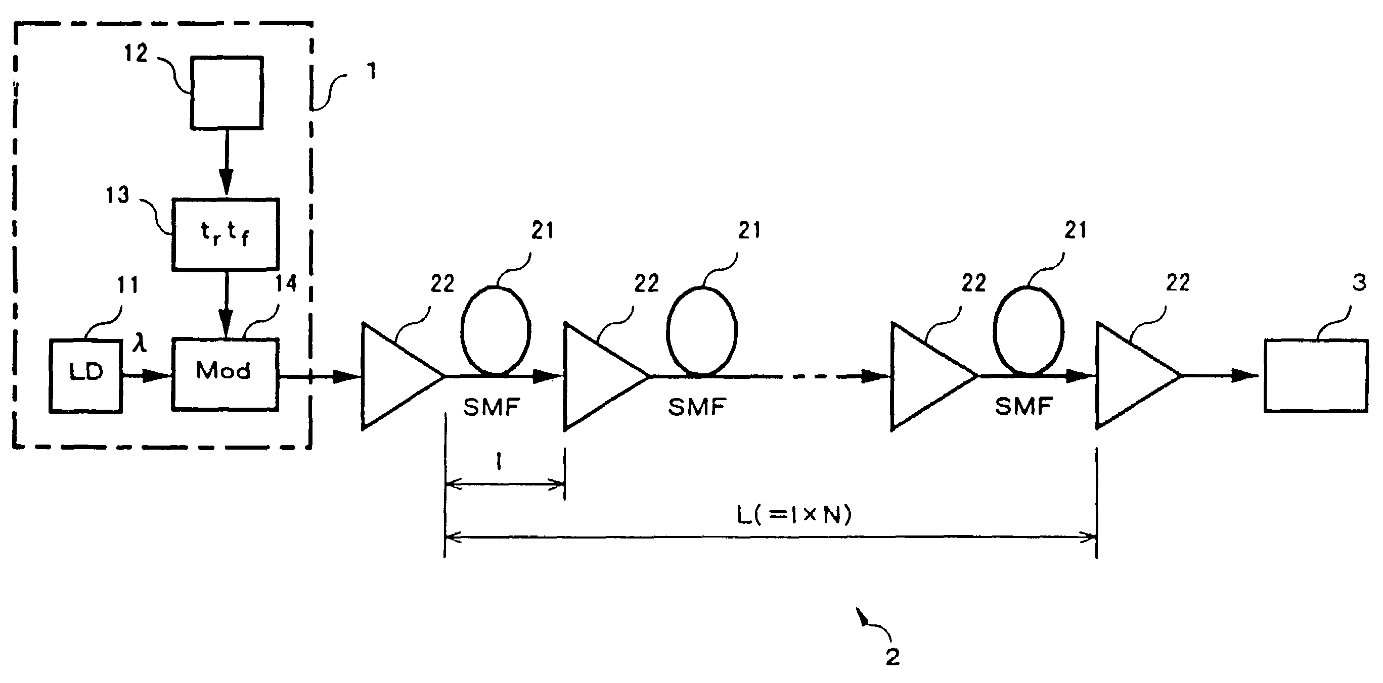
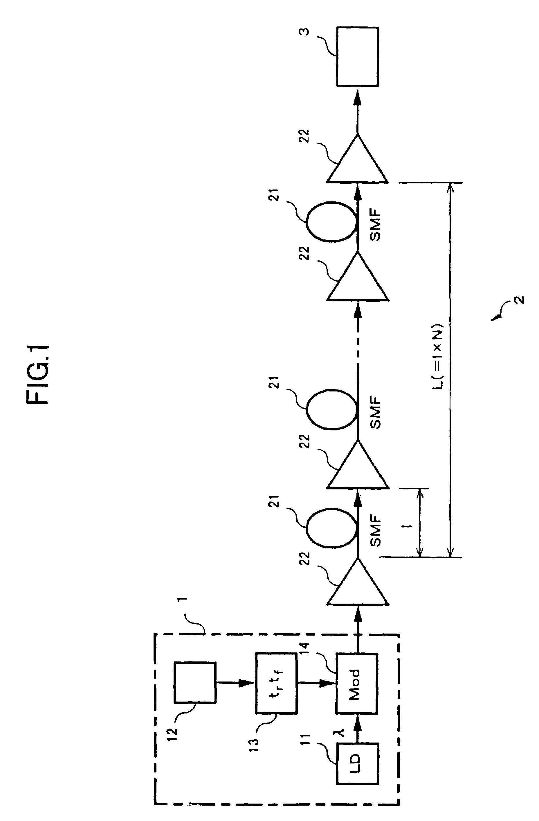
[0032]FIG. 1 is a diagram illustrating an optical communication system, according to an embodiment of the present invention. Referring now to FIG. 1, a transmitting part 1 is an optical transmitting device which generates a signal light with the rise time and fall time thereof being adjusted. Transmitting part 1 sends the adjusted signal light to a transmission path 2. A receiving part 3 is an optical receiving device which receives the signal light transmitted via transmission path 2, and processes the received signal light. Transmission path 2 and receiving part 3 are identical with those adopted in conventional systems, and important aspects of the present invention reside in transmitting part 1.

[0033]Transmitting part 1 includes a light source (LD...


PUM


Abstract

An optical transmission apparatus and method for changing a rise time (tr) and fall time (tf) of a signal light to be transmitted, to reduce wavelength dispersion characteristics and nonlinear effect of a transmission path. A transmitter includes a trtf adjusting circuit capable of adjusting tr and tf of a modulation signal so that the modulation signal is optimized in accordance with reception characteristics. A modulator then modulates a light with this adjusted modulation signal, and the modulated light is then transmitted to a receiver via a transmission path. Therefore, by transmitting the modulated light having changed tr and tf, the influence of wavelength dispersion characteristics and nonlinear effect of the transmission path can be offset, so that the waveform deterioration of signal light after transmission can be reduced.

Description

CROSS-REFERENCE TO RELATED APPLICATIONS[0001]This application is based on, and claims priority to, Japanese application number 10-071525, filed on Mar. 20, 1998, in Japan, and which is incorporated herein by reference.BACKGROUND OF THE INVENTION[0002]1. Field of the Invention[0003]The present invention relates to an optical transmission apparatus and method for restraining influence of wavelength dispersion characteristics or nonlinear effect of a transmission path. More specifically, the present invention relates to an optical transmission apparatus and method which adjusts rise time and / or fall time of signal light to be transmitted, to thereby reduce waveform deterioration of the signal light after transmission.[0004]2. Description of the Related Art[0005]Optical communication systems using fiber optical transmission lines are being used to transmit relatively large amounts of information. However, as users require larger amounts of information to be rapidly transmitted, and as m...

Claims


Application Information

Patent Timeline
Patent Type & Authority Patents(United States)
IPC IPC(8): H04B10/00H04B10/2507H04B10/2525H04B10/255H04B10/40H04B10/50H04B10/524H04B10/54H04B10/58H04B10/60H04J14/00H04J14/02
CPCH04B10/505H04B10/5057H04B10/508H04B10/506H04J14/02
Inventor MIYATA, HIDEYUKINAKAMOTO, HIROSHIONAKA, HIROSHI
Owner FUJITSU LTD
Why Eureka
Try Eureka