Computer controlled multi-stroke cycle power generating assembly and method of operation

Inactive Publication Date: 2006-04-04
SINGH SATNARINE
View PDF16 Cites 34 Cited by
  • Summary
  • Abstract
  • Description
  • Claims
  • Application Information

AI Technical Summary

Benefits of technology

[0014]The present invention is directed towards a computer controlled internal combustion (IC) engine, and its method of operation, designed to operate on a six-stroke cycle and specifically includes the injection of water into the combustion chamber or cylinder of each of a plurality of piston and cylinder assemblies, during a predetermined portion of the six-stroke cycle. More specifically, the quantity and t

Problems solved by technology

Attempts to protect the environment, have resulted in significant improvements in exhaust systems, fuel compositions and other operational components of modern IC engines, which sometimes derogatorily affect the efficiency or performance characteristics of such engines.
However, for the most part, such known attempts have failed to provide an internal combustion engine capable of operating on a six-stroke cycle, which is sufficiently efficient and effective for wide spread commercial use.
However, if the heated water were suddenly to be released from the closed container into atmosphere it would immediately “flash” into steam due to the significant drop in pressure.
Prior attempts to take advantage of the force generated when the water converts to steam in the combustion

Method used


Image

  • Computer controlled multi-stroke cycle power generating assembly and method of operation
  • Computer controlled multi-stroke cycle power generating assembly and method of operation
  • Computer controlled multi-stroke cycle power generating assembly and method of operation

Examples


Embodiment Construction

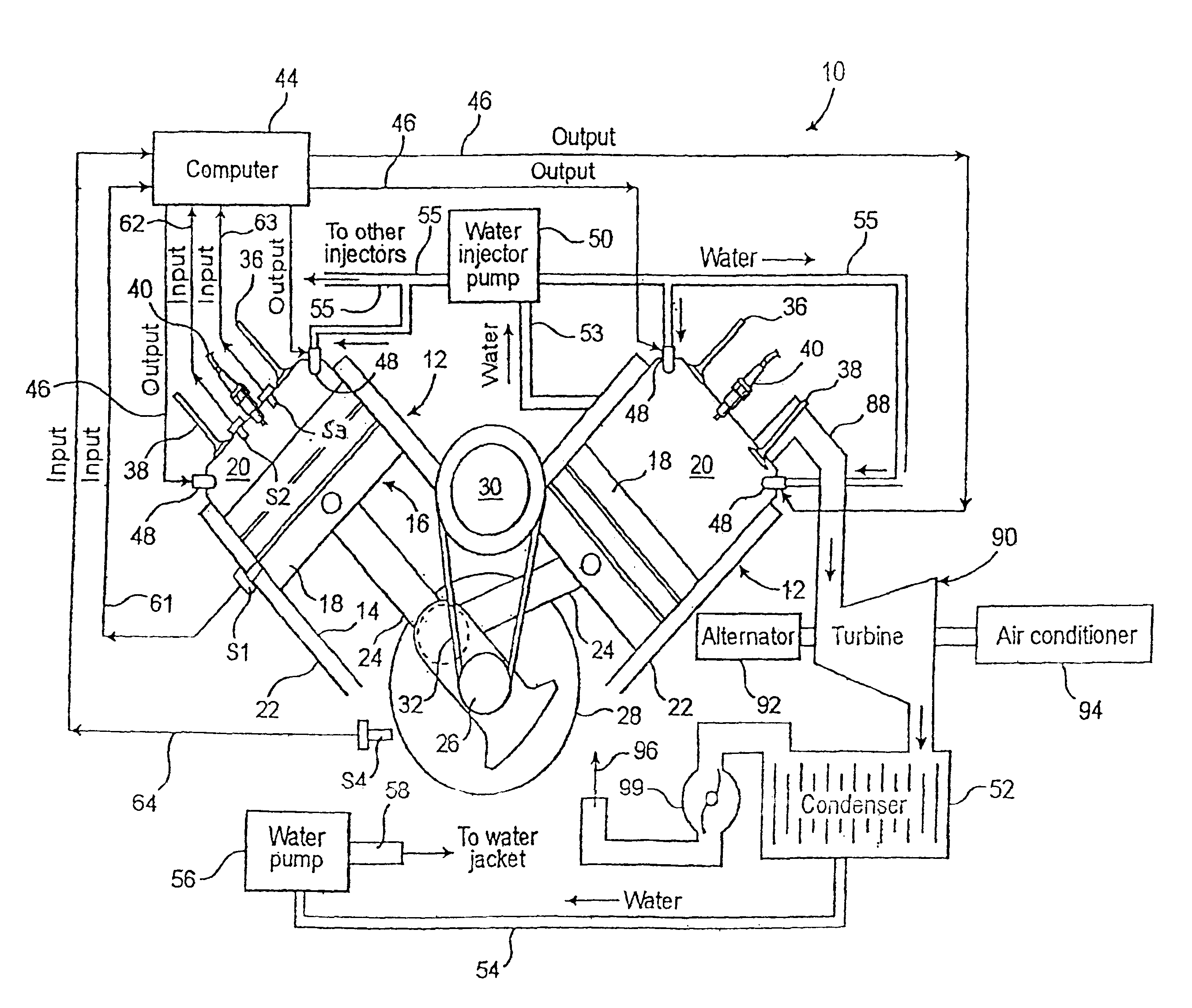
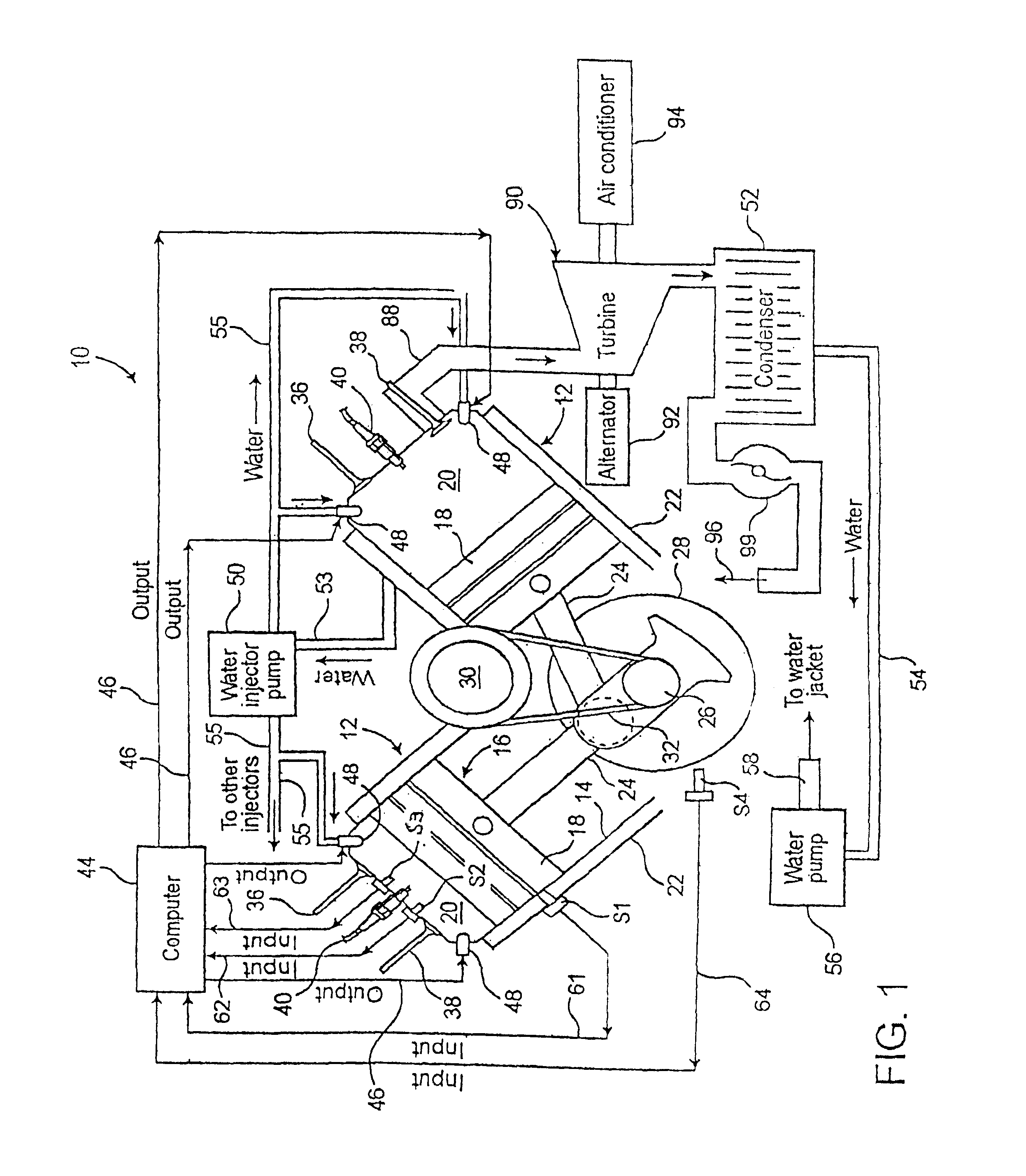
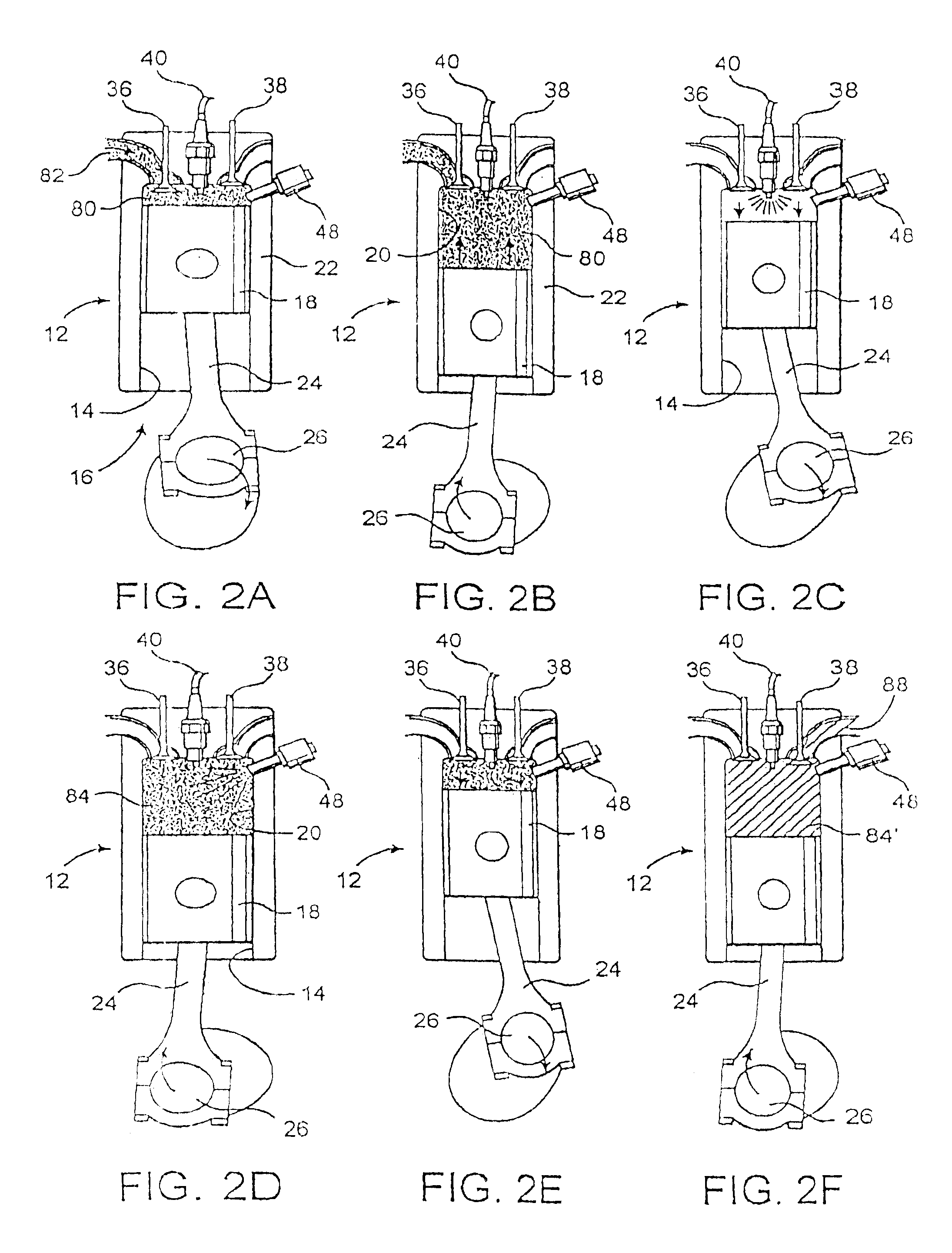
[0045]The present invention is directed towards a computer controlled internal combustion (IC) engine, and its method of operation, wherein the IC engine is designed to operate on a six-stroke cycle and provide an auxiliary power stroke through the regulated injection of water into the combustion chamber or cylinder of one or more piston and cylinder assemblies of the engine and the conversion of the injected water into steam. It is emphasized that while the present invention will be explained primarily with reference to a single piston and cylinder assembly having an at least partially conventional design, the computer controlled IC engine of the present invention may be of the type incorporating one or a plurality of such piston and cylinder assemblies and may be specifically adapted for use as the power source in an automobile, truck or other motorized vehicle.

[0046]With reference to the accompanying Figures, the IC engine of the present invention has a plurality of operative com...


PUM


Abstract

An internal combustion engine and its method of operation including at least one embodiment operating on a six-stroke cycle and including at least one piston and cylinder assembly. The six-stroke cycle includes two power strokes, the latter of which is the result of a water to steam conversion process utilizing the heat of the exhaust gas from the first power stroke. A second embodiment comprises a hybrid power generating assembly incorporating alternative, first and second power sources respectively comprising an internal combustion engine and a water injection engine, the latter of which operates on the water to steam conversion process, wherein the required heat therefore is derived from the exhaust gas of the internal combustion engine. The second power source drives a source of electric energy which powers an electric motor, wherein the electric motor and the internal combustion engine are both connected in driving relation to a power take-off.

Description

CLAIM OF PRIORITY[0001]The present application is a continuation-in-part application of previously filed, currently pending application having Ser. No. 10 / 007,012, filed on Nov. 5, 2001, now U.S. Pat. No. 6,571,749, issued Jun. 3, 2003, which is a continuation-in-part of application Ser. No. 09 / 465329, filed on Dec. 17, 1999, now U.S. Pat. No. 6,311,651 issued on Nov. 6, 2001, wherein all of the above are incorporated herein in their entirety by reference.BACKGROUND OF THE INVENTION[0002]1. Field of the Invention[0003]This invention relates to a computer controlled, internal combustion engine designed to operate on a six-stroke cycle, wherein water is injected into each of the one or more cylinders during a predetermined portion of the six-stroke cycle depending upon the energy content within the cylinder subsequent to ignition of the conventional air-fuel mixture. The residual heat from the ignited air-fuel mixture serves to convert the injected water into steam on a controlled bas...

Claims


Application Information

Patent Timeline
IPC IPC(8): F02B77/00F02B1/04F02B3/06F02B47/02F02B75/02F02F1/24
CPCF02B41/10F02B47/02F02B75/021F02M25/03F02G5/04F02M25/0227F02G5/02F02B1/04F02B3/06F02F2001/247F02G2260/00Y02T10/121Y02T10/163Y02T10/166Y02T10/12
Inventor SINGH, SATNARINE
Owner SINGH SATNARINE
Why Eureka
Try Eureka