Liquid cooling jacket

a cooling jacket and liquid technology, applied in the direction of cooling/ventilation/heating modification, semiconductor devices, lighting and heating apparatus, etc., can solve the problems of increasing resistance, pressure loss, and difficulty in making the coolant flow evenly among the radiating fins, and achieve superior extensibility and assembly, good heat transfer coefficient, and good heat transfer coefficient

Active Publication Date: 2006-04-04
MAXELL HLDG LTD
View PDF15 Cites 37 Cited by
  • Summary
  • Abstract
  • Description
  • Claims
  • Application Information

AI Technical Summary

Benefits of technology

[0013]An object of the present invention is to provide a liquid cooling jacket good in heat transfer coefficient and superior in extensibility and assembling.
[0015](1) According to the present invention, because the coolant flow within the liquid cooling jacket ensures a plurality of passages, the passage resistance is low. In addition, by setting the size of each of the inlet and outlet for the coolant to be substantially equal to the height of the arranged radiating fins, the flow rates between the radiating fins can be even.
[0017](3) According to the present invention, because the route of the coolant is turned back by the partition provided between the radiating fins, the inlet and outlet for the coolant can be arranged in a row and thus convenience on piping is superior.

Problems solved by technology

However, the meandering passage as illustrated in FIG. 18 has a problem that the passage resistance increases as the length of the passage increases, and thus the pressure loss increases.
The passage in which the flow of coolant is divided into a plurality of steams, as illustrated in FIG. 19, has a problem that it is difficult to make the coolant flow evenly among the radiating fins.
More specifically, because any liquid flow has straight motility, there is a problem that the coolant is hard to flow to the radiating fin near the inlet.
As a result, the heat transfer coefficient decreases so that heat from the heating element cannot be efficiently transmitted to the coolant.
The structure as illustrated in FIG. 20 also has a problem that unevenness occurs in the liquid streams 1503a to 1503c between the radiating fins.
As a result, the heat transfer coefficient decreases so that heat from the heating element cannot be efficiently transmitted to the coolant.
In addition, any prior art as described above has a problem that improvement of coefficient of thermal conductivity is difficult even if the jacket size is increased in order to ensure more contact area, because the distance from the centered heating element increases.

Method used


Image

  • Liquid cooling jacket
  • Liquid cooling jacket
  • Liquid cooling jacket

Examples


Embodiment Construction

[0040]Hereinafter, embodiments according to the present invention will be described in detail with reference to drawings. Through all drawings for explaining the embodiments, the same components are denoted as a rule by the same reference numerals, respectively, to omit the repetitious description.

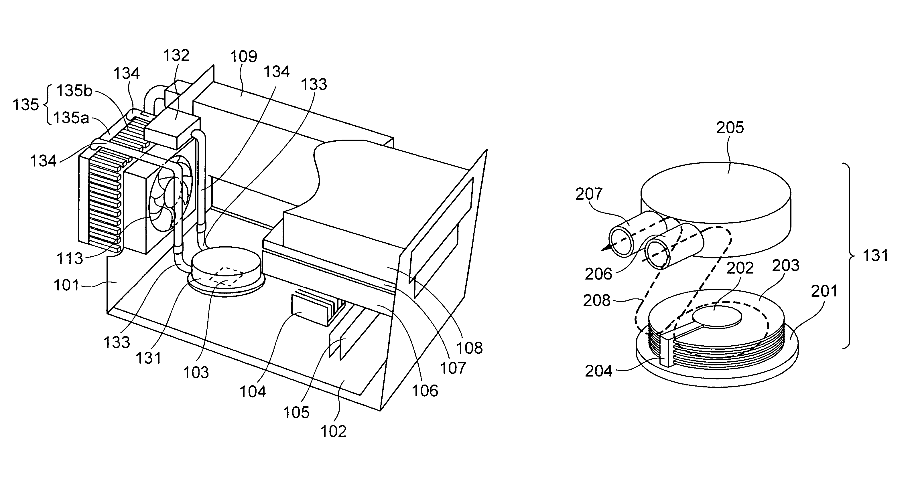
[0041]With reference to FIG. 1, the structure of an electronic device to which a liquid cooling jacket according to the present invention is applied will be described. FIG. 1 is a perspective view of the electronic device to which the liquid cooling jacket according to the present invention is applied. As an example of the electronic device, FIG. 1 illustrates a desktop type personal computer.

[0042]In FIG. 1, a mother board 102 is near the bottom face within a casing 101. On the mother board 102 mounted are a CPU 103 as a heating element, a chip set 104, and a memory 105. An HDD 106, an FDD 107, and a CD-ROM drive 108 are installed as external storage devices within the casing 101. A liqui...


PUM


Abstract

In a liquid cooling jacket, to improve the heat transfer coefficient, extensibility and assembling, the liquid cooling jacket comprises a base bonded to a heating element; a post standing perpendicularly to the base; a plurality of radiating fins attached to the post and arranged so as to be parallel to the base; a partition filling up intervals between the plurality of radiating fins at a predetermined width; and a case which surrounds the post and the radiating fins and is bonded to the base, and to which an inlet and an outlet for coolant are attached at positions where flow of the coolant is divided by the partition. The plurality of radiating fins may be arranged at intervals each of which is narrow in comparison with a thickness of each of the plurality of radiating fins. Therefore, because the coolant flow within the liquid cooling jacket ensures a plurality of passages, the passage resistance is low. In addition, by setting the size of each of the inlet and outlet for the coolant to be substantially equal to the height of the arranged radiating fins, the flow rates on the radiating fins can be even.

Description

CROSS REFERENCE TO RELATED APPLICATION[0001]This application relates to and claims priority from Japanese Patent Application No. 2003-349701, filed on Oct. 8, 2003, the entire disclosure of which is incorporated herein by reference.BACKGROUND OF THE INVENTION[0002]1. Field of the Invention[0003]The present invention relates to a liquid cooling jacket attached to a heating element in a liquid cooling system used for cooling an electronic device.[0004]2. Description of the Related Art[0005]Conventionally, a liquid cooling jacket used for cooling an electronic device must efficiently transmit heat from a heating element to coolant.[0006]For this reason, as an example, a conventional liquid cooling jacket has therein a meandering passage, as illustrated in FIG. 18. In this example, the passage 1302 within the jacket 1301 meanders so that the flow 1303 of coolant is in contact with the jacket 1301 as long as possible. This is a method in which the contact area between the coolant and the...

Claims


Application Information

Patent Timeline
Patent Type & Authority Patents(United States)
IPC IPC(8): F28F7/00F28D15/02H01L23/367H01L23/427H01L23/473H05K7/20
CPCF28D15/02F28F3/02F28F3/12H01L23/3672H01L23/427H01L23/473H01L2924/0002H01L2924/00H05K7/20
Inventor OIKAWA, HIRONORI
Owner MAXELL HLDG LTD
Why Eureka
Try Eureka