Universal depth cut burr having dental and skeletal applications

a universal depth and burr technology, applied in the field of cutting devices, can solve the problems of inherently limited triangular or rectangular cross-section, potential cutting of adjacent tooth surfaces, and inability to meet the needs of patients, so as to reduce the diameter of the crown and/or lateral portion, reduce the risk of cutting into internal tissue and nerves, and reduce the effect of crown and/or lateral dental surfaces

Inactive Publication Date: 2006-04-04
CALDWELL MARK J
View PDF28 Cites 23 Cited by
  • Summary
  • Abstract
  • Description
  • Claims
  • Application Information

AI Technical Summary

Benefits of technology

[0013]The abrasive burr end is rigidly joined at the junction and includes a selected length having a cylindrical cross-section extended to a distal burr end. The burr length and distal burr end includes an abrasive exterior surface of sufficient hardness to cut tooth enamel. The burr junction defines a stop of minimal diameter for providing a self-limiting depth of penetration of the burr length and distal burr end into the patient's tooth enamel during shank rotation. The curved shoulder and the junction are positioned to be in contact against adjacent tooth surfaces during rotation of the burr, thereby limiting the depth of penetration of the burr length and burr end for reducing and shaping selected dental surfaces of the patient's crown and lateral dental surfaces of any maxillary or mandibular tooth.
[0014]Another embodiment provides a universal orthopedic joint depth cut burr including an abrasive burr end having a self-limiting depth of penetration for application in reducing and shaping a convoluted bone surface. The burr includes a shank end releasably connectable to a drill, an elongated cylinder having a first diameter, and a shank second end having a chamfered rim angled radially inwardly to a lesser second diameter. A curved shoulder is extended from the chamfered rim in a uniformly decreasing cross-sectional diameter extending to a distal end forming a junction having a circular cross-section of a lesser third diameter than the chamfered rim. The curved shoulder and chamfered rim are aligned axially with the axis of the shank for balanced rotation thereof.
[0015]An abrasive burr end is rigidly joined at the junction and includes a selected length having a cylindrical cross-section extended to a distal burr end. The burr length and distal burr end includes an abrasive exterior surface of sufficient hardness to provide precise cuts in convoluted exterior surfaces of skeletal bone. The burr junction defines a stop providing a self-limiting depth of penetration of the burr length and distal burr end into the convoluted surfaces of skeletal bone during shank rotation. The curved shoulder and the lesser diameter of the junction are readily positioned in contact against adjacent uncut bone surfaces during rotation of the shank and burr end, thereby precisely self-limiting the depth of penetration to the selected length of the burr end, while allowing unhindered viewing along the length of the shank and burr end during a method of size reduction of convoluted exterior bone surfaces proximal of joint surfaces.

Problems solved by technology

Unfortunately, if the operator of the reduction burr applies undue pressure on the shank of the burr, the working surface of the burr will readily penetrate past the preferred depth thereby cutting through additional enamel or bone, with a risk of cutting into internal tissue and nerves.
Use of a reduction burr having an intermediate positioned flange of conical, triangular or rectangular cross-section is inherently limited to cutting applications against occlusal dental surfaces lacking steep cusps due to the increased cross-sectional width of the conical, triangular or rectangular flange.
The width of an intermediate flange denies seating between steeply sloped cusps, denies seating on molar inclines, and denies insertion laterally between adjacent teeth while potentially cutting the adjacent tooth surface.
In addition, the width of the conical, triangular or rectangular flange is not utilizable against convoluted joint surfaces having limited widths therebetween.
Frequent changing of reduction burr bits between ones having intermediate flanges and bits having generally straight sides is time consuming, requires unpleasant inactive periods for the patient, and increases a risk of selection of reduction burr bits having inappropriate cutting depths other than the target depth of reduction.
Further, if the perimeter of an intermediate flange, whether conical, triangular or rectangular in cross-section, is not perfectly concentric, then the rotational balance of the burr bit is disturbed with creation of vibration and wobble in the distal burr bit when rotated at 30,000 rpm or higher rpm.
If vibration and wobble is present but not visible to the dentist or orthopedist, the vibration transmitted through the burr end can create fractures in the tooth enamel or in the ossiferous surfaces.
A limitation to the use of a burr having a perpendicular flange is that the burr is not easily maintained in a level orientation when moved along the patient's convoluted lateral dental surfaces, therefore generating grooves in the enamel surface having uneven depths.
Further, prior reduction burrs having perpendicular flanges of significantly larger diameter relative to the shank diameter and burr end diameter can easily obstruct the dental practitioner's view of the burr end during manipulation of a drill within the patient's mouth.
Intermittent obstruction of a burr end during application against a dental surface by a significantly larger diameter perpendicular flange leads to mistakes in achieving optimal reduction depths for convoluted dental surfaces.

Method used


Image

  • Universal depth cut burr having dental and skeletal applications
  • Universal depth cut burr having dental and skeletal applications
  • Universal depth cut burr having dental and skeletal applications

Examples


Embodiment Construction

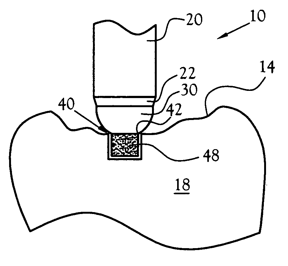
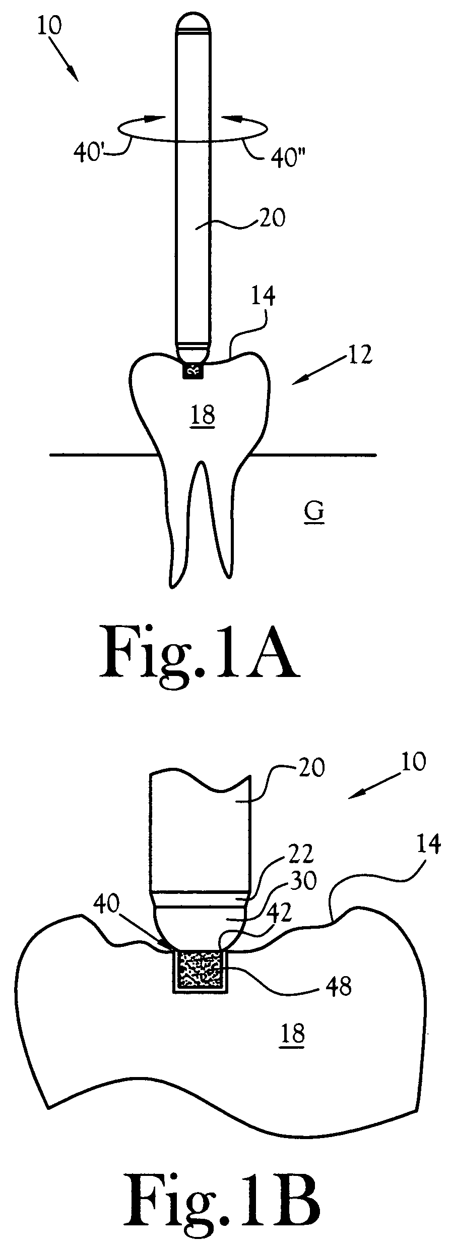
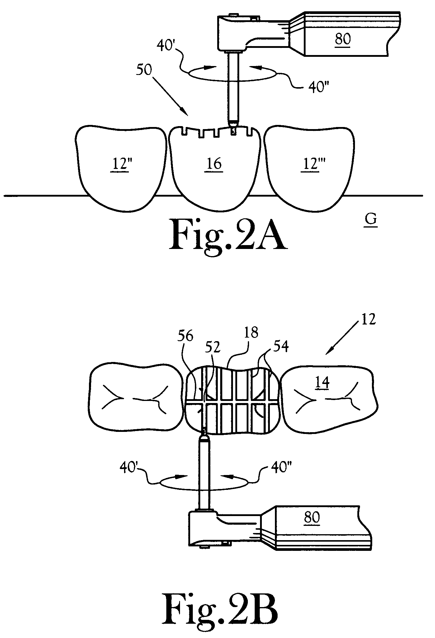
[0032]In accordance with the present invention, a reduction burr 10 is disclosed that provides a self-limiting stop mechanism for limiting the depth of penetration of the burr abrasive surfaces during cutting and reduction of a patient's dental surfaces of a tooth 12 (see FIGS. 1A and 1B). The reduction burr 10 is universally applied to readily reduce all dental surfaces requiring fabrication during tooth restoration, including the crown surface 14, also identified herein as the occlusal surface, the lingual side surface (tongue side) 16, the buccal side surface (cheek side) 18, and either or both lateral surfaces extended between the lingual and buccal side surfaces and disposed proximal of adjacent teeth 12″, 12′″. The reduction burr 10 disclosed herein is highly maneuverable and positionable to provide precise cuts 50, lateral grooves 58, and precise surface reductions for all tooth surfaces 12 disposed above the patient's gingival epithelium (gums) G.

[0033]The self-limiting dept...


PUM


Abstract

A reduction burr for universal application for depth reduction of dental or ossiferous surfaces includes a shank of a first diameter extended to a chamfered rim angled radially inwardly to a smaller second diameter. A curved shoulder extended from the chamfered rim decreases in cross-sectional diameter to a distal end having a third diameter. A burr end having an abrasive surface thereon is extended from a junction with the shoulder distal end to a distal burr end, with the abrasive surface having sufficient hardness to cut enamel or ossiferous surfaces. The junction defines a precise stop for self-limiting the burr penetration depth into the enamel or ossiferous surfaces due to the greater second diameter of the curved shoulder contacting against adjacent uncut surfaces. A method of size reduction is disclosed for universal application of a reduction burr to precisely reduce enamel or ossiferous surfaces in both lateral and longitudinal directions.

Description

CROSS REFERENCE TO RELATED APPLICATIONS[0001]Not ApplicableSTATEMENT REGARDING FEDERALLY SPONSORED RESEARCH OR DEVELOPMENT[0002]Not ApplicableBACKGROUND OF THE INVENTION[0003]1. Field of Invention[0004]This invention pertains to cutting devices for use in dental and orthopedic applications. More particularly, this invention pertains to a universal depth cut burr for use in shaping dental surfaces and / or skeletal surfaces, and methods of application thereof.[0005]2. Description of the Related Art[0006]In the fields of dentistry and orthopedic medicine, precise cutting and shaping instruments are frequently utilized such as drill bits and rotary cutting tools. For dental reduction and joint repair applications, efficient and compact cutting surfaces are required for drill bits and rotary cutting tools, which are referred to hereinafter as a cutting burr or a reduction burr. A cutting burr or reduction burr must provide a precise cut having a preferred width, length, and an exact depth...

Claims


Application Information

Patent Timeline
Patent Type & Authority Patents(United States)
IPC IPC(8): A61C3/06A61B17/16A61B19/00A61C1/08A61C3/02
CPCA61B17/1673A61C3/02A61C1/082A61B2019/306A61B2090/036
Inventor CALDWELL, MARK J.
Owner CALDWELL MARK J
Why Eureka
Try Eureka