Method and apparatus for bonding polarizing plate

a technology of polarizing plate and apparatus, which is applied in the direction of polarizing elements, instruments, other domestic objects, etc., can solve the problems of reducing yield, unable to be reloaded or transported with an acceptable operating convenience, and inability to shorten the time, so as to achieve the effect of prohibiting stop marks and easy exercise of control of the direction of the axis of light transmission of the polarizing pla

Inactive Publication Date: 2006-04-04
FUJIFILM CORP +1
View PDF10 Cites 55 Cited by
  • Summary
  • Abstract
  • Description
  • Claims
  • Application Information

AI Technical Summary

Benefits of technology

[0007]Meanwhile, in the phase difference film, bonded in use to e.g., a polarizing plate forming the LCD with a view to optical compensation, such as prevention of coloration or enlarging the field of view, it is required to set the axis of orientation at various angles relative to the axis of light transmission of the polarizing plate. Up to now, such a system is used which consists in punching off the rim of a film, such as a PET film, obtained on longitudinal or transverse uniaxial stretching, so that the axis of orientation is at a preset inclination relative to the sides of the polarized plate, thus lowering the yield, as in the case of the polarizing plate.
[0014]It is a first object of the present invention to provide a method and an apparatus for bonding a polarizing plate which are superior in the operating efficiency and in the yield of the polarizing plate.
[0015]It is a second object of the present invention to provide a method and an apparatus for bonding a polarizing plate in which a composite film composed of the phase difference film and the polarizing plate bonded together may be produced at a high yield.
[0016]It is a third object of the present invention to provide a method and an apparatus for bonding a polarizing plate in which cutting chips are not liable to be intruded into a spacing between the substrate and the film even when the film is cut directly before bonding.
[0017]It is a fourth object of the present invention to provide a method and an apparatus for bonding a polarizing plate in which roll exchange operations may be carried out easily.
[0019]It is a sixth object of the present invention to provide a method and an apparatus for bonding a polarizing plate in which, when bonding the polarizing plate to each substrate surface, control on the direction of the axis of light transmission of the polarizing plate can be exercised easily.

Problems solved by technology

However, with the method of bonding the pieces of the polarizing plate one-by-one on the LCD, these pieces of the polarizing plate need to be re-loaded, or the release film needs to be peeled off, directly before bonding these pieces of the polarizing plates to the substrate, so that the process time cannot be shorter beyond a certain limit value.
On the other hand, the piece of the polarizing plate is usually punched from the polarizing plate film in the roll form and hence tends to roll on itself with the consequence that it cannot be re-loaded or transported with an acceptable operating convenience.
In particular, there is raised a problem that, if a large size polarizing plate is used in keeping up with the increasing LCD image format, the yield is concomitantly lowered.
The cut ends of the polarizing plate, not used for bonding, are hardly re-usable because plural sorts of the material are used in combination, as a result of which the amount of waste materials is increased.
This problem is presented common in case the pieces of the polarizing plate are bonded one-by-one to the LCD.

Method used


Image

  • Method and apparatus for bonding polarizing plate
  • Method and apparatus for bonding polarizing plate
  • Method and apparatus for bonding polarizing plate

Examples


examples

[Examples]

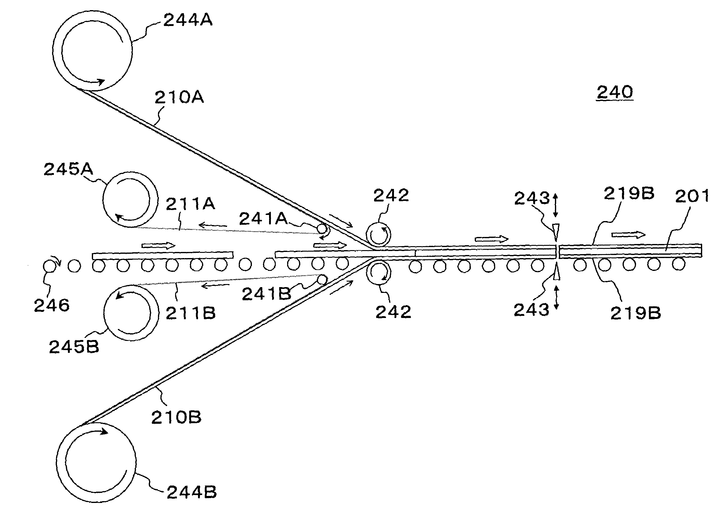
[0166]Referring to the drawings, an example of the present invention (first solution) is explained. FIG. 13 is a side view schematically showing the structure of a polarizing plate bonding apparatus according to an example of the present invention (first solution). This polarizing plate bonding apparatus 170 includes a reel-out means 171, a first payout roll 172, a second payout roll 173, a film transporting conveyor 174, a cutting means 175, a film piece transporting conveyor 176, a separating roll 177, a third payout roll 178, a fourth payout roll 179, a takeup means 180, a first substrate transporting conveyor 181, a first position guide means 182, a receiving roll 183, a pressure bonding roll 184, a second substrate transporting conveyor 185, a second position guide means 186, an encoder, a film piece position sensor, a substrate positioning member and a control means.

[0167]The substrate (120 of FIG. 13), used here, is a flat-plate-shaped rectangular liquid crystal dis...


PUM

PropertyMeasurementUnit
angleaaaaaaaaaa
angleaaaaaaaaaa
angleaaaaaaaaaa

Abstract

Method and apparatus for bonding a polarizing plate high in operating efficiency and yield. The apparatus includes a cutting unit for cutting at least a polarizing plate of a strip-shaped film, composed of the polarizing plate and a release film bonded to the polarizing plate, leaving the release film uncut, when a forward end side pre-severed end face of the strip-shaped film perpendicular to the longitudinal direction of the strip-shaped film has traveled up to a length corresponding to a length of a substrate, to form a film piece, a release film separating unit for separating the release film from the film piece thus severed, and a bonding unit for bonding the tacky surface of the film piece freed of the release film to a mating position of the substrate so that the forward end side end face of the transported substrate is parallel to the pre-severed end face of the film piece.

Description

FIELD OF THE INVENTION[0001]This invention relates to a method and an apparatus for bonding a polarizing plate to a substrate. This invention also relates specifically to a method and an apparatus for bonding a polarizing plate to each of both surfaces of the substrate and, more specifically, to a method and an apparatus for continuously bonding the polarizing plates.BACKGROUND[0002]As a liquid crystal display apparatus, referred to below as LCD, is coming into widespread use, the demand for a polarizing plate is increasing rapidly. In general, a polarizing plate film includes a polarizing layer, exhibiting a light polarizing capability, and a protective film(s) bonded to one or both surfaces thereof (see FIG. 14(B)). As the material for the polarizing layer, polyvinyl alcohol, referred to below as PVA, is predominantly used. A polarizing film for a polarizing layer is formed by uniaxially stretching a PVA film, dyeing the resulting polarizing film with iodine or a dichroic dye and ...

Claims


Application Information

Patent Timeline
Patent Type & Authority Patents(United States)
IPC IPC(8): G02F1/01B32B37/18G02F1/13B32B37/22B32B38/00B32B38/18G02B5/30G02F1/1335
CPCB32B37/182G02B5/3033G02F1/1303G02F1/133528B32B37/223Y10T156/1339B32B38/0004B32B38/1858B32B2457/20B32B2457/202Y10T156/125Y10T156/12Y10T156/1075Y10T156/1085Y10T156/1322Y10T156/171Y10T156/1317Y10T156/1705Y10T156/1082Y10T156/1064Y10T156/1707Y10T156/1343G02F1/13
Inventor KANBARA, TAKAYUKISAKAI, NAOKISUGIHARA, RYOICHI
Owner FUJIFILM CORP
Why Eureka
Try Eureka