Combustor linear and method for making thereof

a technology of linear and combustor, which is applied in the direction of manufacturing tools, light and heating equipment, turbines, etc., can solve the problems of increasing the manufacturing cycle time needed to produce liners, the liners are costly to be brazed,

Inactive Publication Date: 2006-04-04
GENERAL ELECTRIC CO
View PDF18 Cites 4 Cited by
  • Summary
  • Abstract
  • Description
  • Claims
  • Application Information

AI Technical Summary

Problems solved by technology

A large proportion of liners joined in this manner, in some instances over 90%, exhibit defects such as voids in the braze joints, which require a second braze operation involving the application of more slu...

Method used


Image

  • Combustor linear and method for making thereof
  • Combustor linear and method for making thereof
  • Combustor linear and method for making thereof

Examples


Embodiment Construction

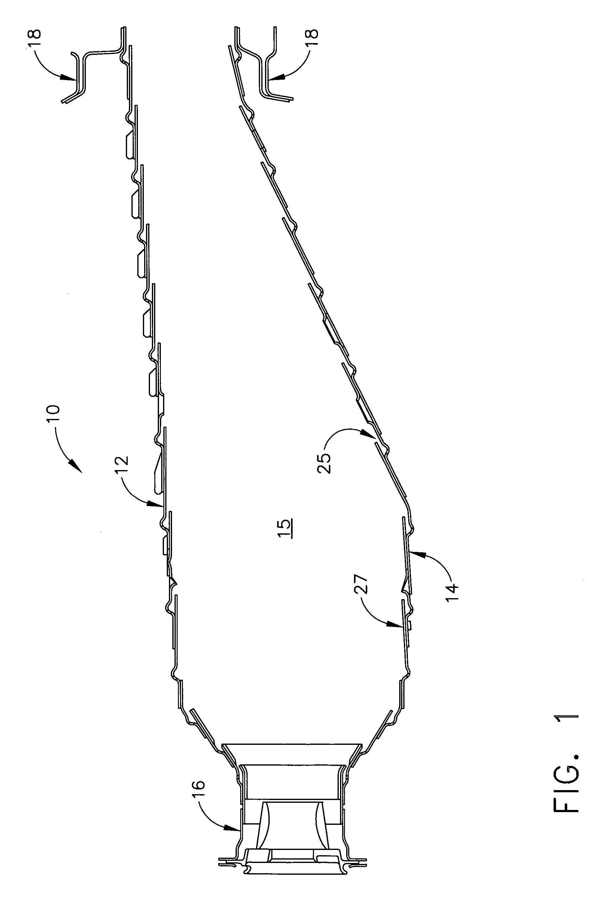
[0014]Referring to the drawings wherein identical reference numerals denote the same elements throughout the various views, FIG. 1 illustrates an exemplary combustor 10. The illustrated combustor 10 is of annular design which has a central axis 11 (shown in FIG. 5) coincident with the longitudinal axis of a gas turbine engine (not shown) when assembled, although the present invention is equally applicable to other types of combustors having liners disposed about an axis. The combustor 10 has circumferentially extending outer and inner liners 12 and 14, which define an annular combustion chamber 15. the liners 12 and 14 are connected at their forward ends by an annular dome assembly 16. Each liner has a mounting flange 18 attached to its aft end. Film cooling of the liners 12 and 14 is provided by a plurality of cooling slots 25, which are described in more detail below.

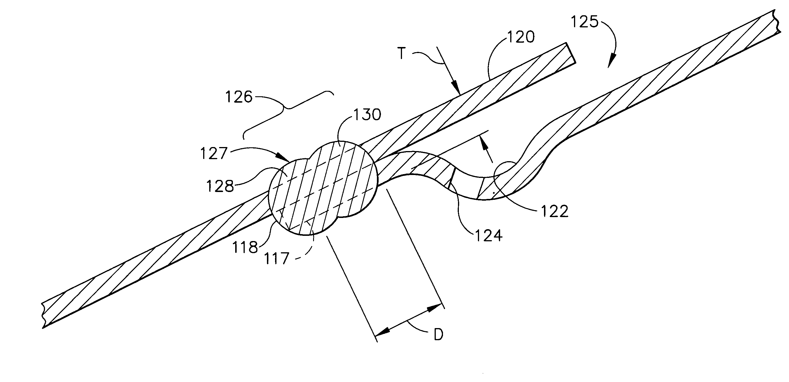
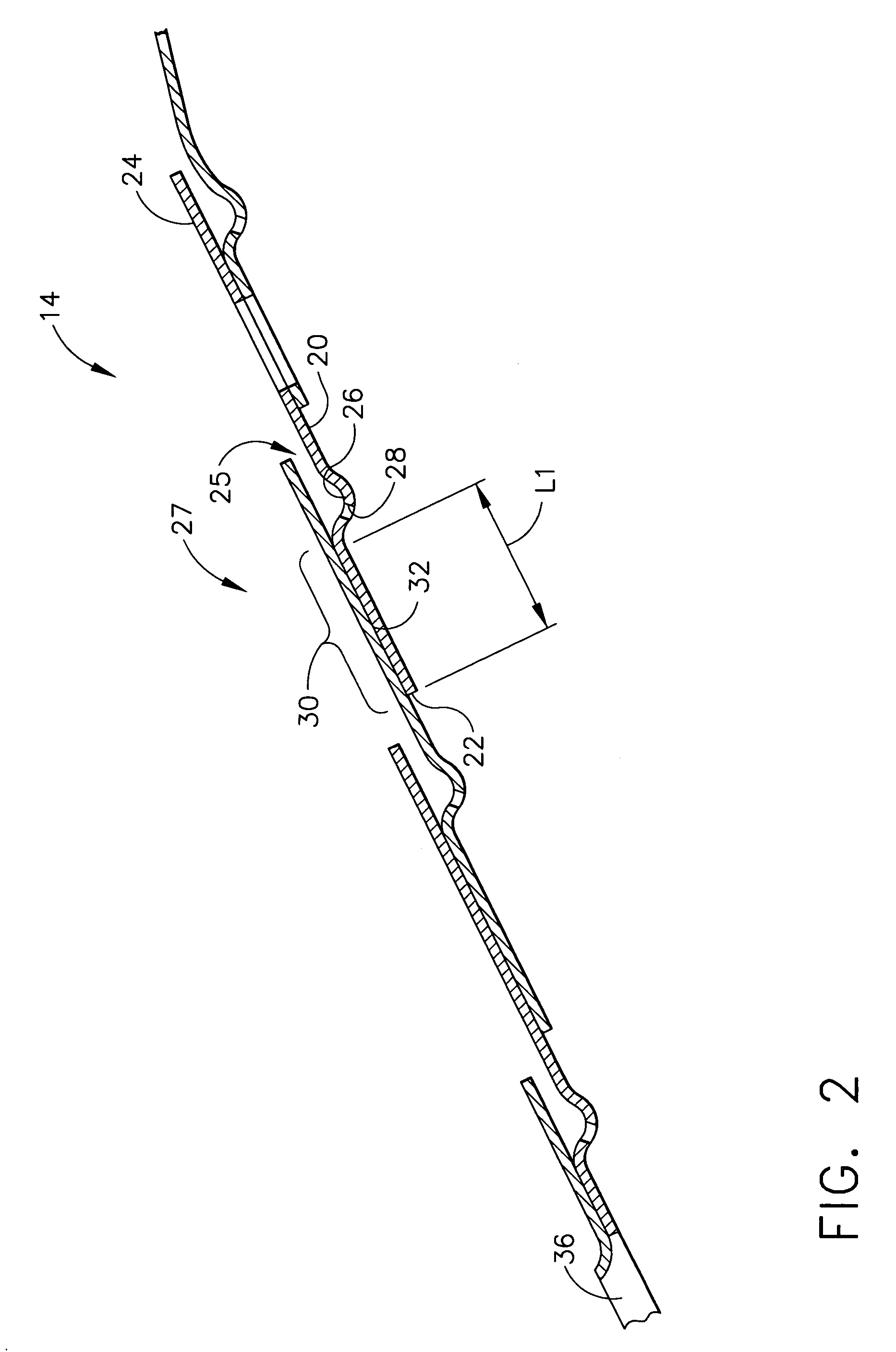
[0015]Referring now to FIG. 2, an inner liner 14 constructed in accordance with the prior art is illustrated. It sh...


PUM

PropertyMeasurementUnit
Lengthaaaaaaaaaa
Areaaaaaaaaaaa
Circumferenceaaaaaaaaaa

Abstract

A combustor liner is provided having first and second annular bands which define an overlapping circumferential joint area, wherein a weld is disposed in the joint area encompassing substantially all of the axial length of the joint area. A method for producing such a combustor liner is also provided.

Description

CROSS REFERENCE TO RELATED APPLICATIONS[0001]This application is a Division of application Ser. No. 10 / 028,028, filed Dec. 21, 2001 now U.S. Pat. No. 6,651,437.[0002]This invention relates generally to combustor liners for gas turbine engines and more particularly to liners which are assembled from a plurality of annular bands.[0003]A gas turbine engine includes a compressor that provides pressurized air to a combustor wherein the air is mixed with fuel and ignited for generating hot combustion gases. These gases flow downstream to one or more turbines that extract energy therefrom to power the compressor and provide useful work such as powering an aircraft in flight. Combustors used in aircraft engines typically include inner and outer combustor liners to protect the combustor case and surrounding engine components from the intense heat generated by the combustion process.[0004]One particular type of combustor liner is comprised of a plurality of annular sheet metal bands that are ...

Claims


Application Information

Patent Timeline
IPC IPC(8): B23K26/00B23K26/24F23R3/00
CPCB23K26/246F23R3/002B23K2201/001B23K26/244B23K2101/001
Inventor FARMER, GILBERTGROESCHEN, JAMES A.REDDEN, RONALD D.DEVANE, SHAUN M.
Owner GENERAL ELECTRIC CO
Why Eureka
Try Eureka