Sensor using roof mirror/roof prism array scale, and apparatus equipped with the sensor

a technology of prism array scale and sensor, which is applied in the direction of lenses, instruments, optical elements, etc., can solve the problems of increasing power consumption, increasing power consumption in a similar manner, and complicated apparatus as a whole, and achieves low power consumption and favorable gap characteristics.

Inactive Publication Date: 2006-04-04
CANON KK
View PDF5 Cites 17 Cited by
  • Summary
  • Abstract
  • Description
  • Claims
  • Application Information

AI Technical Summary

Benefits of technology

[0041]An object of the present invention is to provide, in compliance with the three-grating-type principle and, in particular, using the reflection-type construction, an encoder having a favorable gap characteristic, and to realize (1) miniaturization of an apparatus and (2) low power consumption that are the aforementioned technical problems.
[0042]Another object of the present invention is to provide, by realizing (1) and (2), an optical encoder that simultaneously satisfies various requirements such as the following: (3) to facilitate embedding into a device, (4) to be capable of performing high-resolution position detection, and (5) to perform high-accuracy position detection.
[0043]Still another object of the present invention is to provide, as means for solving the aforementioned problems, a reflection scale that improves light usage efficiency using a novel grating shape and to provide an optical arrangement that is optimum for the reflection scale.
[0044]Still further another object of the present invention is to provide a displacement measuring apparatus that is capable of detecting displacement information containing the moving direction of a moving body with high precision and at high resolution by obtaining a plurality of displacement signals having different phases, where overall simplification, miniaturization and reduction in power consumption of the apparatus is realized by utilizing the novel shape and pitch of the grating portion of the reflection scale and by appropriately setting arrangements and the like of the reflection scale, the light-emitting element of a light source, and a light-receiving element.

Problems solved by technology

Accordingly, it is required to increase the intensity of light emitted from the light source, which results in an increase in power consumption.
This leads to a situation where the light does not become a substantially effective light beam, which also results in an increase in power consumption in a like manner.
As a result, the apparatus becomes complicated as a whole.
With the construction shown in FIG. 32 in which a lens is provided, there is obtained a result that is favorable in terms of the light intensity shortage problem but unfavorable in terms of miniaturization.
If the distance between the lens and the light source is shortened and the lens curvature is reduced in order to realize miniaturization and thickness reduction, it is required to increase the accuracy of optical axis matching, which means that there are imposed limitations on size and thickness reduction.
In order to enhance the accuracy and resolution, a higher-accurate lens performance is required, which hinders the realization of cost reduction.
Also, as can be seen from these drawings, a light beam on the optical axis of the light source is not made incident on the light-receiving portion, so that it is impossible to say that there is obtained sufficient light usage efficiency.
If a current injected into the light source element is increased in order to obtain required intensity of received light with this construction, the current density is increased because the light-emitting region is minute, so that there may occur breakage of the elements.
As a result, there is no choice but to limit the injection current.
As described above, in the reflection-type encoder in compliance with the three-grating-type principle, if a half mirror or the like is used as a reflecting means / construction, the apparatus size is increased, which has lead to a difficulty in realizing miniaturization up to now.
Also, if there is made an attempt to realize miniaturization, it becomes impossible to effectively use on-axis rays of a light source, as can be seen from FIGS. 28, 31, 33, and 34.
As a result, there occurs a shortage of light intensity.
In addition, the usage of a lens is conceivable as a measure to increase the light intensity, although this construction departs from the originally intended three-grating-type detecting principle and there occurs a problem concerning a position detecting function.

Method used


Image

  • Sensor using roof mirror/roof prism array scale, and apparatus equipped with the sensor
  • Sensor using roof mirror/roof prism array scale, and apparatus equipped with the sensor
  • Sensor using roof mirror/roof prism array scale, and apparatus equipped with the sensor

Examples


first embodiment

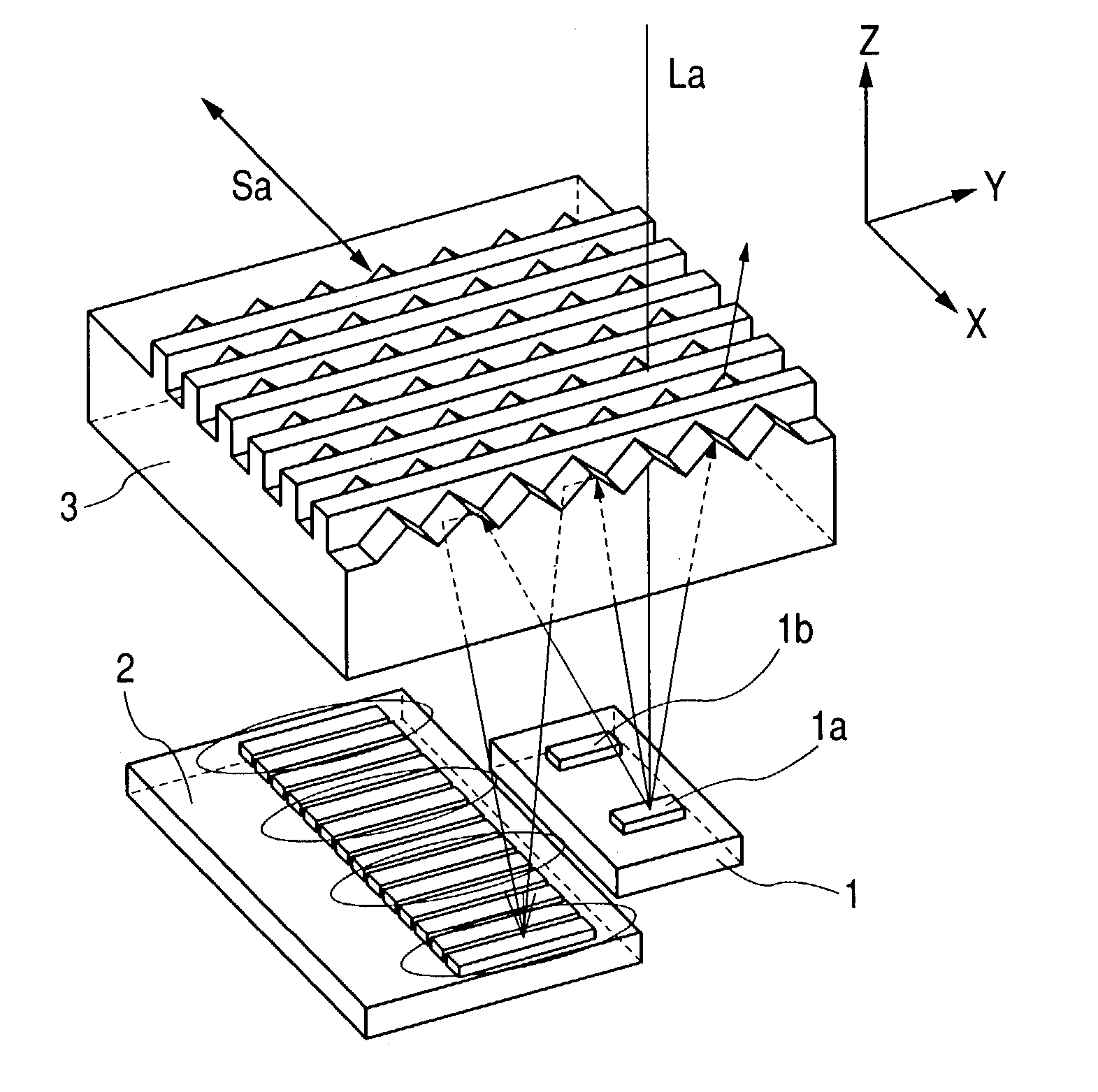
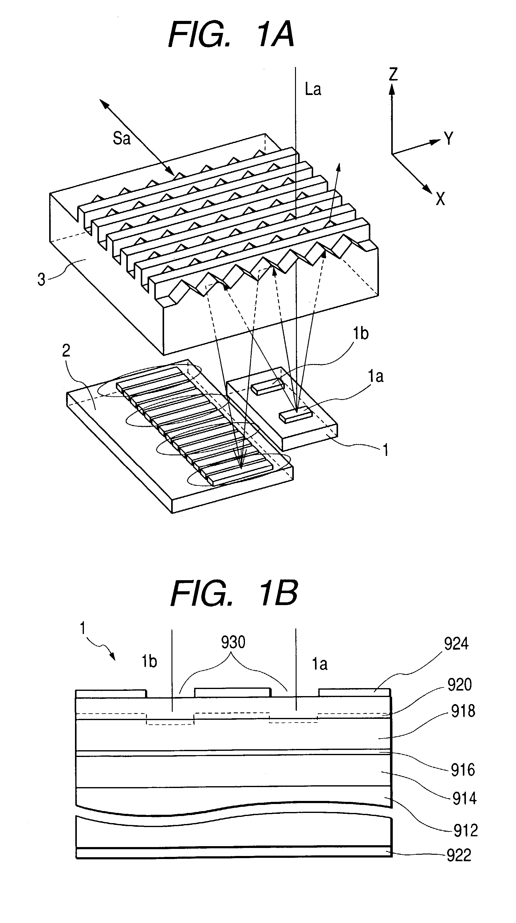
[0097]FIG. 1A is a perspective view of the main portion of an optical system of a first embodiment that uses an optical-reflection-type linear scale of the present invention. First, there will be briefly described (1) a light source means and a light-receiving means and (2) a reflection scale in this order.

(1) Light Source Means, Light-receiving Means

[0098]In this drawing, reference numeral 1 denotes a multi-point light emission LED of a current constricting type that functions as a light source means and is a light-emitting diode having a current constricting structure with which current is concentrated in a limited light-emitting region, reactive current is reduced, and there is taken out light. The light source 1 has a construction where a plurality of light-emitting regions are provided on a semiconductor substrate.

[0099]In this embodiment, there are provided two light-emitting regions that are a light-emitting region 1a and a light-emitting region 1b. The light source 1 radiate...

second embodiment

[0202]A second embodiment differs from the first embodiment described above only in a size relation in a manner described below.

[0203]In this second embodiment, only P1 and P2 are changed and other sizes are completely the same as those in the first embodiment.

[0204]It is assumed that P1 that is the pitch of the MRA scale is approximately equal to 42 μm, while P2 that is the arrangement pitch of the array-shaped light source / the pitch between the segments (S1, S2, and S3) of the photodiode array is approximately equal to 84 μm.

[0205]Here, a preferable gap setting position will be calculated by concretely assuming important numerical values in the second embodiment, as is the case of the first embodiment described above.

[0206]From the disclosed relational expression, the gap V(=U), with which an optimum interference fringe contrast is obtained through air conversion, becomes as follows when n that is a natural number is set at “1”.

[0207]U=⁢2⁢nP12 / λ=⁢2×(42×42÷0.65)≈⁢5,428⁢⁢µm

[0208]FIG...

third embodiment

[0212]A third embodiment differs from the first embodiment only in a size relation in a manner described below, as is the case of the second embodiment.

[0213]In this second embodiment, only P1 and P2 are changed and other sizes are completely the same as those in the first embodiment.

[0214]It is assumed that P1 that is the pitch of the MRA scale is approximately equal to 21 μm, while P2 that is the arrangement pitch of the array-shaped light source / the pitch between segments (S1, S2, and S3) of the photodiode array is approximately equal to 42 μm.

[0215]Here, a preferable gap setting position will be calculated by concretely assuming important numerical values in the third embodiment, as is the case of the first embodiment described above.

[0216]From the disclosed relational expression, the gap V(=U), with which an optimum interference fringe contrast is obtained through air conversion, becomes as follows when n that is a natural number is set at “1”.

[0217]U=⁢2⁢nP12 / λ=⁢2×(21×21÷0.65)≈...


PUM


Abstract

A divergent light beam from a light source unit having a plurality of light-emitting regions is almost contained within the surface of a reflecting body that is an array of micro roof mirrors / roof prisms disposed in a regular manner. The light beam emitted from the light source unit with an angle of divergence is reflected by the reflecting body and is almost converged on a light-receiving surface. As a result, there is increased the ray density of a light beam on the light-receiving surface.

Description

BACKGROUND OF THE INVENTION[0001]1. Field of the Invention[0002]The present invention relates to a displacement measuring apparatus, and in particular to a displacement measuring apparatus, such as a linear encoder or a rotary encoder, that detects displacement information, such as the moving amount, moving speed, and rotation speed, of a moving body using an optical scale.[0003]2. Related Background Art[0004]There has conventionally been used a displacement measuring apparatus that detects displacement information of a moving body using three optical scales.[0005]Such a displacement measuring apparatus is proposed in Japanese Patent Publication No. 60-23282, Japanese Utility Model Application Laid-Open No. 1-180615 , and the like, for instance.[0006]There will be described below conventional encoders disclosed in these patent documents that each use three gratings.[0007]First, FIGS. 26 and 27 are each a schematic drawing showing the main portion of an optical system of the displace...

Claims


Application Information

Patent Timeline
Patent Type & Authority Patents(United States)
IPC IPC(8): G01D5/34G01B11/00G01D5/347G01D5/38G02B3/06G02B3/08G02B5/08G02B5/10G02B5/124G02B7/08
CPCG01D5/38G01D5/34715
Inventor IGAKI, MASAHIKOATSUTA, AKIO
Owner CANON KK
Why Eureka
Try Eureka