Subsurface conductivity imaging systems and methods

a conductivity imaging and subsurface technology, applied in the field of subsurface conductivity imaging systems and methods, can solve the problems of logistically difficult implementation of such an array, complication in dc resistivity measurement, and difficulty in providing sufficient current for a large array

Inactive Publication Date: 2006-04-04
SCHLUMBERGER TECH CORP
View PDF28 Cites 71 Cited by
  • Summary
  • Abstract
  • Description
  • Claims
  • Application Information

AI Technical Summary

Problems solved by technology

In addition, for many applications, it is difficult and costly to provide sufficient current for a large array.
One complication in DC resistivity measurement arises when the sub-bottom (e.g., beneath the sea floor) is layered.
The implementation of such an array is logistically difficult because significant lengths of cables must be moved for each individual measurement.
However, the actual data collection and analysis to derive the resistivity distribution is limited by the underlying physics and the practical considerations of making measurements (e.g., spacing and cable length).
In addition, current density falls off quickly with distance when using a dipole transmitter.
Except for surveys to recover the resistivity of shallow depths, such arrays of current and potential electrodes are impractical (uneconomic) on land, but practical and feasible on the sea bottom as described herein.
These natural fields may be noise for the dc method or for the controlled source em methods (below).
Unfortunately, this discrete sampling approach is not satisfactory if the near surface is highly inhomogeneous.
This results in static offsets that pose significant problems in interpreting the MT data.
Unfortunately dense coverage on land is often precluded by practical problems of access, powerline noise, habitation etc.
This type of MT system typically relies on acoustic positioning in deep water, and, thus, may suffer from positioning errors.
If the secondary fields are small, it may be technically difficult to measure them in the frequency domain because of the presence of much larger primary field.
Although the inhomogeneity in the formation may create higher wave numbers from the natural fields, such low order wave number field cannot provide coverage as wide as that provided by the controlled source.
A thin resistive layer can pose a difficult problem for MT measurements because it can reduce signal magnitudes beyond detection by MT as the layer resistivity increases.
Thus, while a thin resistive layer may pose a problem for measurements using DC or low frequency sources (e.g., MT), it poses little problem for measurements using high frequency sources (e.g., CSEM).
The cost of creating arrays of such transmitters on land is uneconomical.
However, interpretation of subsurface features based on multiple measurements from a single large source often leads to ambiguities that render the method useless.
Nevertheless, these systems provide a lesson, albeit costly, on the importance of wide spatial coverage for both transmitters and receivers.
The insights gained from surface CSEM systems are not applicable and the inverted boundary conditions alter the sensitivity of the fields to the sub-bottom resistivity as they do for MT.
However, on land, it is not practical to measure the electric field continuously (e.g., with a large number of densely-packed sampling points), nor is it practical to move the transmitting electrodes continuously as would be necessary if the subsurface were to be “illuminated” by all possible configurations of the injected currents.
Because of the difficulties in obtaining data for continuous coverage surveys on land, prior art methods instead use discrete arrays in which current injection and voltage measuring electrodes are regularly spaced, typically along a profile.

Method used


Image

  • Subsurface conductivity imaging systems and methods
  • Subsurface conductivity imaging systems and methods
  • Subsurface conductivity imaging systems and methods

Examples


Embodiment Construction

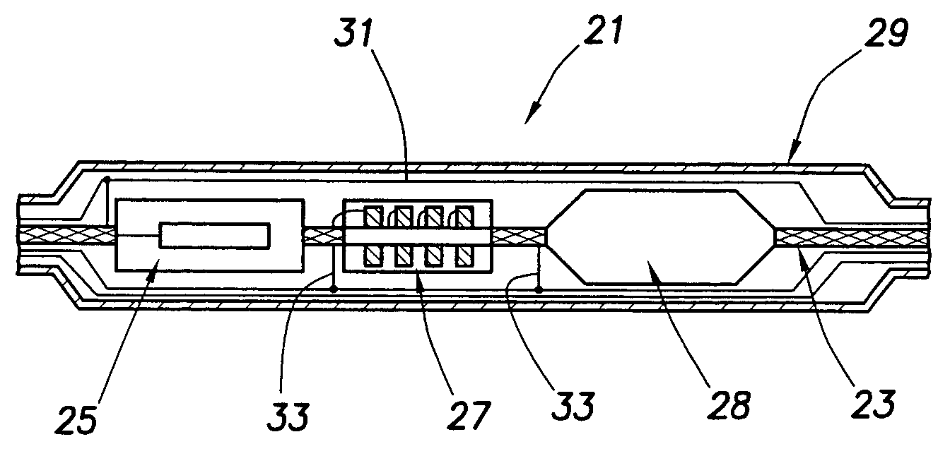
[0077]The theory and practice of the above methods for mapping the distribution of electrical conductivity of the earth formations form the basis of the present invention. The present invention relates to methods and apparatuses that use a high degree of spatial coverage to provide information about the resistivity distribution. In particular, the present invention provides methods that can be used in inhomogeneous formations. In one embodiment, the present invention provides a measurement system that includes several resistivity methods in a single sensor array to determine resistivities of the earth formations.

[0078]The spatial configurations of the inducing currents or fields, and of the secondary fields, in these methods may be described by their spatial Fourier transforms. Accordingly, the subsurface conductivity distribution may be described by a superposition of spatial sinusoids known as wavenumbers, which are the spatial equivalents of the frequencies in temporal variation....


PUM


Abstract

A subsurface imaging cable includes a plurality of sensor modules, wherein the plurality of the sensor modules are flexible and each of the plurality of the sensor modules is spaced apart on the subsurface imaging cable at a selected distance; and a flexible medium connecting the plurality of the sensor modules, wherein the subsurface imaging cable is flexible and adapted to be wound on a reel. A method for subsurface images includes acquiring direct-current measurements at a plurality of sites in a survey area; acquiring a first set of electric and magnetic measurements from natural electromagnetic fields at the plurality of sites; acquiring a second set of electric and magnetic measurements using controlled electric and magnetic sources at the plurality of sites; and determining a subsurface conductivity distribution from the direct-current measurements and the first set and the second set of electric and magnetic measurements.

Description

FIELD OF THE INVENTION[0001]The present invention relates to methods and apparatuses for imaging subsurface resistivities.BACKGROUND OF THE INVENTION[0002]Hydrocarbon exploration typically involves various geophysical methods to detect the presence of hydrocarbons in the natural void space of the rock (measured as “porosity”) or to map structural features in a formation of interest which are capable of trapping hydrocarbons.[0003]To be mapped geophysically, the formation containing the hydrocarbon must possess a physical property contrast that the geophysical method responds to. For example, seismic waves reflect off interfaces between rock types that have different seismic impedance (the product of velocity and density). The velocities of seismic waves traveling in a medium depend primarily on the elastic constant and density of the medium (e.g., rocks). The density of the medium in turn depends on the porosity and fluid content. The seismic wave velocity is sensitive to porosity, ...

Claims


Application Information

Patent Timeline
Patent Type & Authority Patents(United States)
IPC IPC(8): G01V3/00G01V3/08G01V3/12G01V11/00
CPCG01V3/12G01V3/083
Inventor NICHOLS, EDWARD
Owner SCHLUMBERGER TECH CORP
Why Eureka
Try Eureka