Locking system, especially for motor vehicles

a technology for locking systems and motor vehicles, applied in transmission systems, alarms, transmissions, etc., can solve the problems of limiting the options of arranging the switching element in the lock, unable to ensure the security against the switching element being manipulated, and the magnetic tappet acting directly on the switching element, etc., to achieve reliable resetting of the switching element, reliable steering wheel locking arrangement, and functional reliability and security against theft for the motor vehicle using the lock according to

Inactive Publication Date: 2006-04-04
MARQUARDT GMBH SCHLOSSTRASSE 16 7201 RIETHEIM-WEILHEIM 1 WEST GERMANY
View PDF14 Cites 22 Cited by
  • Summary
  • Abstract
  • Description
  • Claims
  • Application Information

AI Technical Summary

Benefits of technology

[0017]The advantages which are obtained by the invention reside, in particular, in the fact that the functional reliability and security against theft for the motor vehicle using a lock according to the invention is [sic] increased. In particular, the manipulation of the switching element, and therefore also of the “key inserted” signal, on removal of the key from the holder is made more difficult. The arrangement for the actuation of the switching element is not prone to error. A more reliable resetting of the switching elements on removal of the key from the holder is obtained compared to previous ignition locks, thereby also ensuring reliable triggering of the steering wheel locking arrangement. An SMD key having an enclosed switching system can be used as the switching element. There is then no risk of a damaging ingress of foreign bodies into the switching element, even under severe operating conditions. The arrangement according to the invention is very fail-safe and, in addition, can be realized simply and cost-effectively.

Problems solved by technology

Furthermore, it is disadvantageous that the magnetic tappet acts directly on the switching element.
This firstly restricts the options for arranging the switching element in the lock.
Secondly, the security against the switching element being manipulated is likewise not ensured.

Method used


Image

  • Locking system, especially for motor vehicles
  • Locking system, especially for motor vehicles
  • Locking system, especially for motor vehicles

Examples


Embodiment Construction

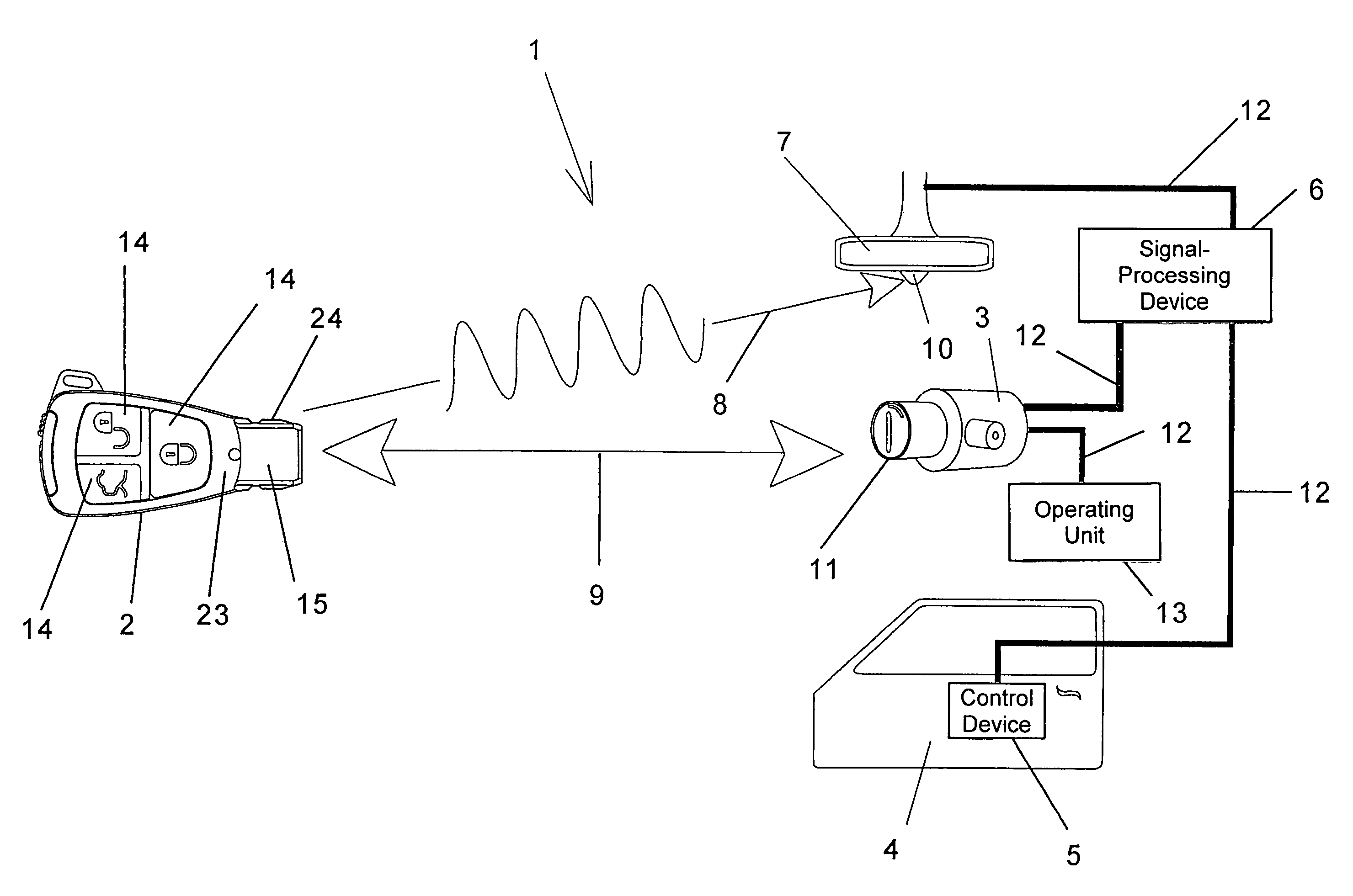
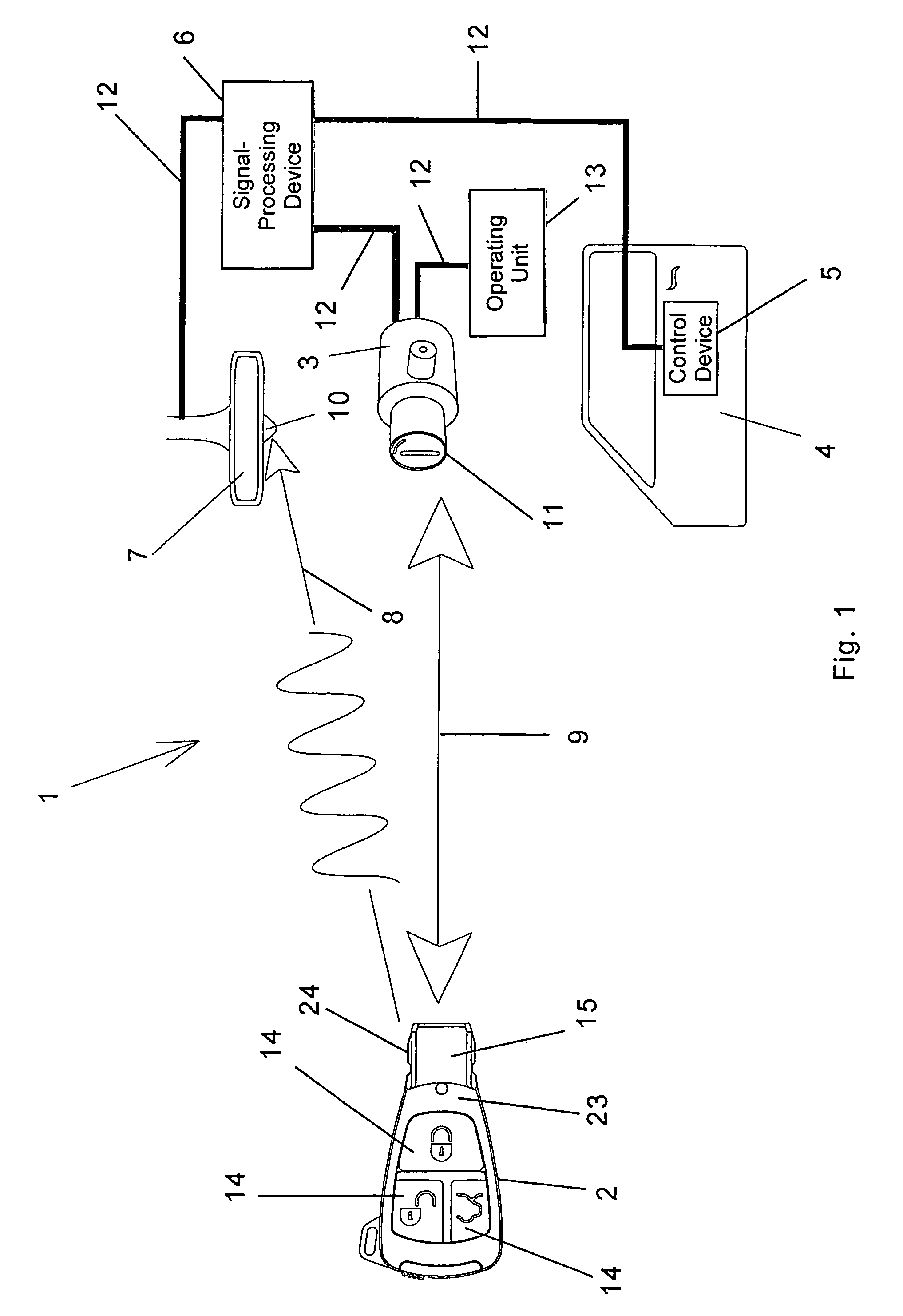
[0027]In FIG. 1, a locking system 1 which is intended for a motor vehicle is shown schematically in accordance with some of its functions. The locking system 1 comprises an electronic lock 3, to be precise an electronic ignition lock and an associated electronic key 2. The lock 3 is connected to an associated operating unit 13, for example an engine controlling means, an electronic immobilizer or the like of the motor vehicle, via a bus system 12, such as the known CAN bus.

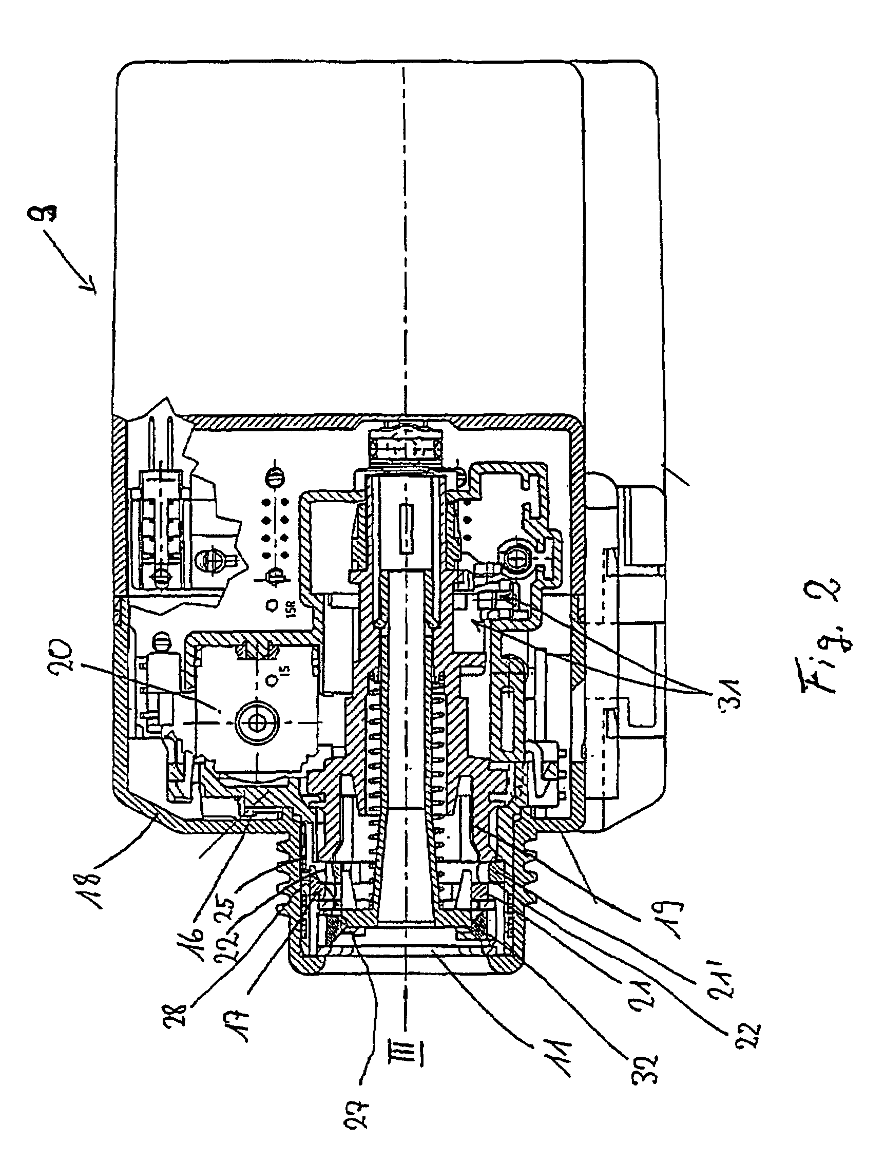
[0028]In order to start up the motor vehicle, for example to start the engine of the motor vehicle, the key 2 is introduced by its front part 15 into a holder 11 of the blocked lock 3. This movement for introducing the key 2 is transmitted to a switching element 16 which is situated in the lock 3 and can be seen in FIG. 3, with the result that the switching element 16 is actuated and produces a signal. This switching element 16 is the so-called “key inserted” switch which is actuated by the introduction of the key...


PUM


Abstract

The invention relates to an electronic lock for a locking system, in particular an electronic ignition lock for a motor vehicle. The lock has a holder into which an associated electronic key can be introduced. The key, which is in the holder, exchanges at least one coded operating signal with the lock. After positively evaluating the operating signal, the holder can be moved into at least one actuating position. The lock has a blocking element which adjusts on introduction of the key into the holder and/or removal of the key from the holder. Movement of the holder is possible when the key is correctly in the holder. Furthermore, the lock has a switching element on which the adjusting movement of the blocking element exerts a switching action via a separate transmitter which can be brought into operative connection both with the blocking element and with the switching element.

Description

BACKGROUND OF THE INVENTION[0001]The invention relates to an electronic lock in accordance with the preamble of patent claim 1.[0002]An electronic lock of this type is used in motor vehicles as an electronic ignition lock for operating an associated operating unit, such as an engine controlling means, an immobilizer or the like.[0003]WO 95 / 09746 discloses a locking system for a motor vehicle, which comprises an electronic lock and an associated electronic key. The lock has a holder into which the key can be introduced. Situated in the lock is a switching element (merely indicated schematically) which can be actuated by the movement of the key as it is being introduced into the holder. The actuation of the switching element, whose switching signal can be interpreted as a “key inserted” signal, then switches on the normal operation of key and lock, the key in the holder exchanging at least one coding operating signal with the lock. After positive evaluation of the transmitted operatin...

Claims


Application Information

Patent Timeline
Patent Type & Authority Patents(United States)
IPC IPC(8): H04B3/00B60R25/06B60R25/02B60R25/04B60R25/20B60R25/24
CPCB60R25/04B60R25/248B60R25/24B60R25/2063Y10T70/5942
Inventor GEIGER, AUGUSTMULLER, KARLGEBER, MICHAELFITZ, HARTMUT
Owner MARQUARDT GMBH SCHLOSSTRASSE 16 7201 RIETHEIM-WEILHEIM 1 WEST GERMANY
Why Eureka
Try Eureka