
Method and apparatus for dark field interferometric confocal microscopy

Inactive Publication Date: 2006-04-04
ZETETIC INST
View PDF58 Cites 7 Cited by
  • Summary
  • Abstract
  • Description
  • Claims
  • Application Information

AI Technical Summary

Benefits of technology

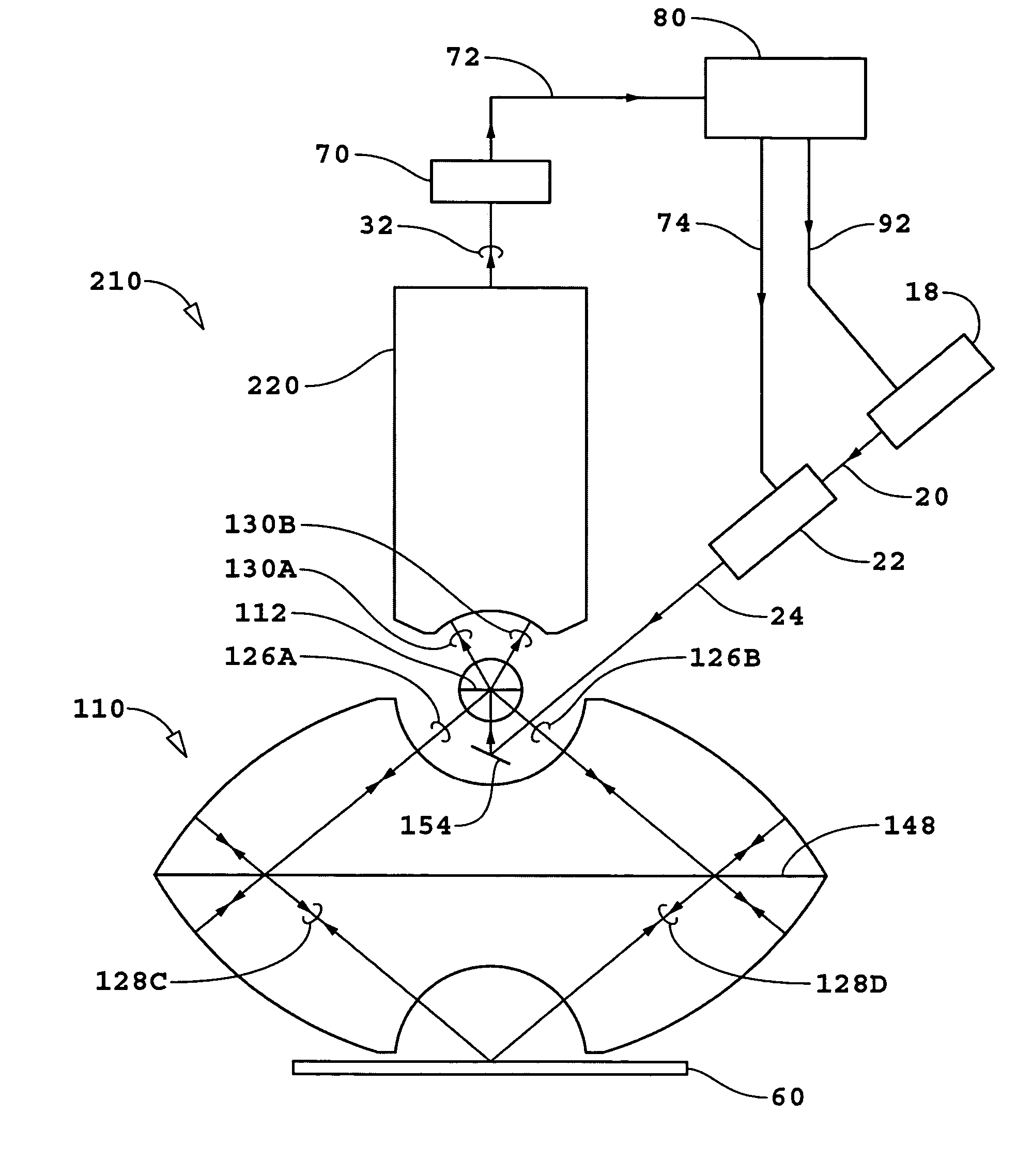
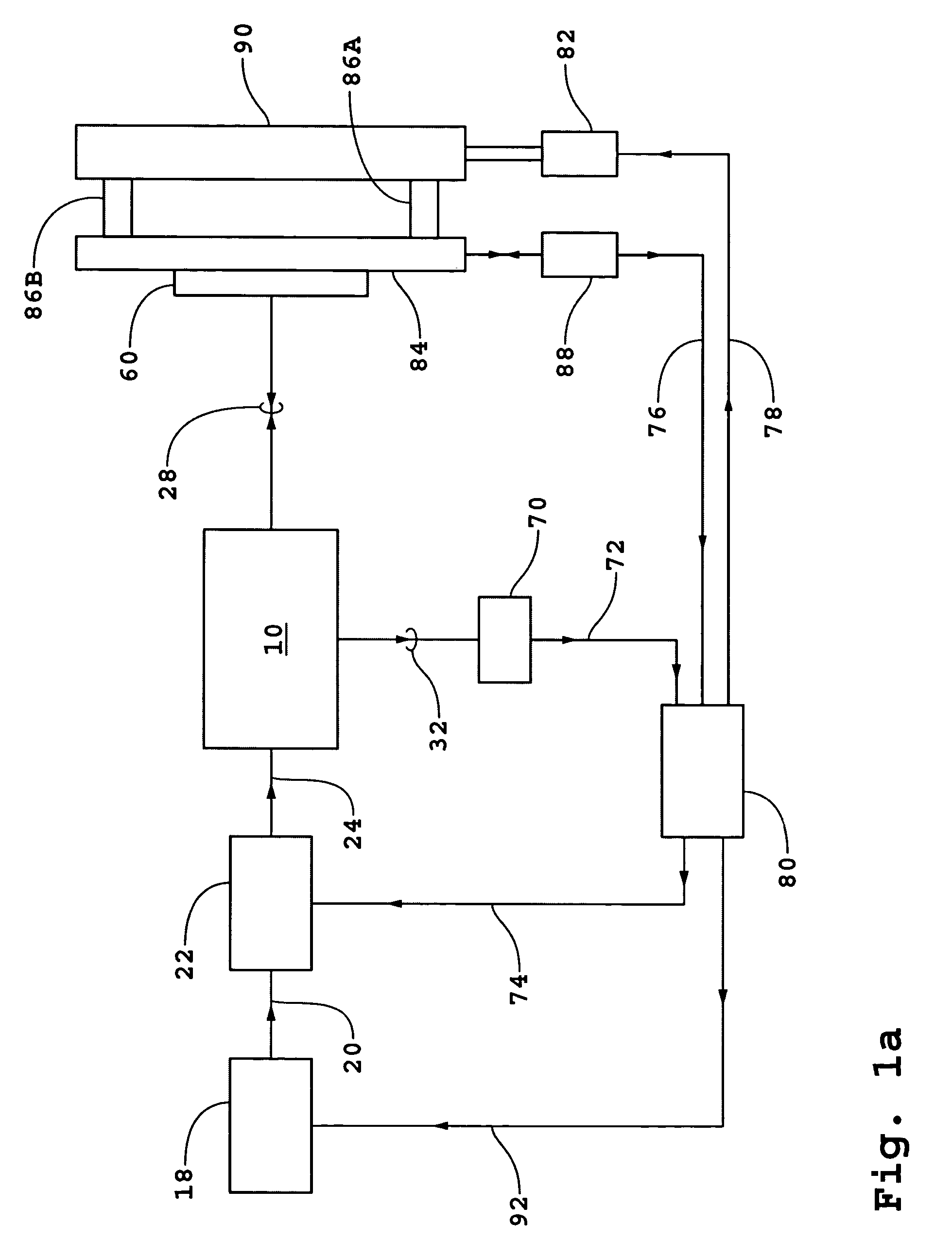
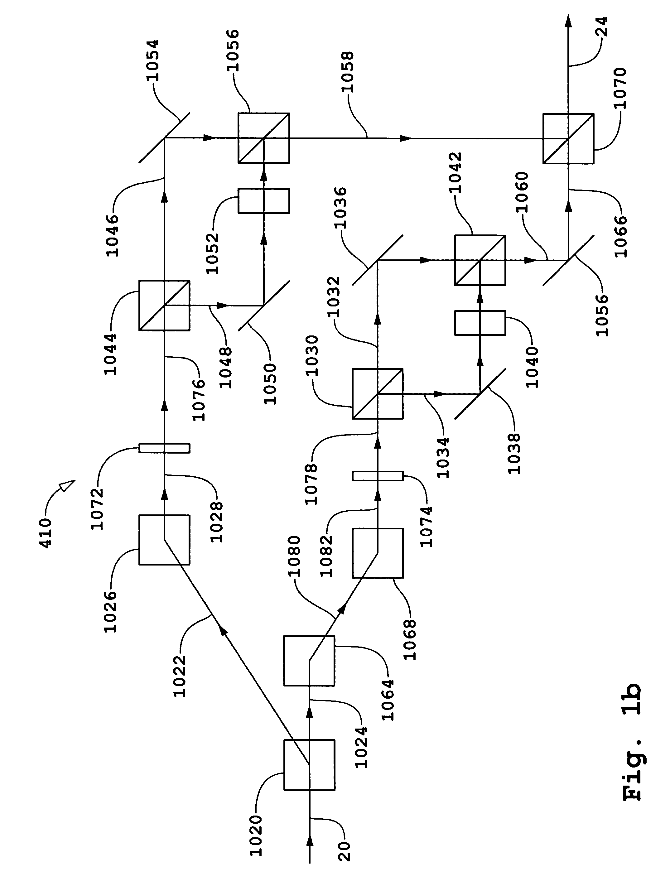
"The present invention is a microscope system that uses interferometric confocal microscopy to measure objects with high resolution. The system includes a source-side pinhole array and a detector-side pinhole array, as well as an interferometer that produces two sets of measurement beams that are focused onto the same object. The system can measure properties of a thin film on the surface of a substrate with a lateral spatial resolution of the same order of magnitude as the imaging system. The system can also measure the reflection / scattering properties of the substrate for different reflection / scattering or transmission polarization states of the measurement beam. The invention also includes a differential interferometric confocal microscope for measuring an object in a dark field mode."

Problems solved by technology

Also, prior art does not teach how to practice dark field differential interferometric confocal microscopy wherein an array of conjugated quadratures of fields are measured jointly, where the components of each conjugated quadratures may be measured jointly, where each conjugated quadratures represents a difference of conjugated quadratures of fields of converging beams subsequently scattered / reflected from a common location on a substrate surface wherein one of the converging beams subsequently scattered / reflected or transmitted by the location is focused to an image plane located above the substrate surface and the second of the converging beams subsequently scattered / reflected or transmitted by the location is focused to an image plane located below the substrate surface, and where the nominal values of the conjugated quadratures of the array of conjugated quadratures is zero, i.e., the field that is being measured is nominally dark.

Method used


Image

  • Method and apparatus for dark field interferometric confocal microscopy
  • Method and apparatus for dark field interferometric confocal microscopy
  • Method and apparatus for dark field interferometric confocal microscopy

Examples


first embodiment

[0044]There will be a restriction on the duration or “pulse width” of a beam pulse τp1 produced by source 18 as a result of the continuous scanning mode used in the third variant of the Pulse width τp1 will be a parameter that in part controls the limiting value for spatial resolution in the direction of a scan to a lower bound of

τp1V,  (1)

where V is the scan speed. For example, with a value of τp1=50 nsec and a scan speed of V=0.20 m / sec, the limiting value of the spatial resolution τp1V in the direction of scan will be

τp1V=10 nm.  (2)

[0045]Pulse width τp1 will also determine the minimum frequency difference that can be used in the bi- and quad-homodyne detection methods. In order that there be no contributions to the electrical interference signals from interference between fields of conjugated quadratures, the minimum frequency spacing Δfmin is expressed as

[0046]Δ⁢⁢fmin>>1τp1.(3)

For an example of τp1=50 nsec, 1 / τp1=20 MHz.

[0047]For certain embodiments, the frequencies of input b...

second embodiment

[0163]The reduction of statistical error is also a direct consequence of operation in the dark field mode. The contributions of background fields are removed / eliminated in the second embodiment by the superposition of background fields arranged to have the same amplitudes and phase differences of π and not by the subtraction of intensities. As a result of the dark field, the intensity of beam 24 can be increased significantly without saturation of detector 70 and a corresponding reduction in statistical error is achieved.

[0164]The increase in throughput is a direct consequence of operating in a dark field mode. The time required to achieve a certain precision in the measured array of conjugated quadratures is reduced by an increase of the intensity of beam 24 that is permitted by operating in the dark field mode. As a result of the dark field, the intensity of beam 24 can be increased significantly without saturation of detector 70.

[0165]Also when operating in a dark field mode, a m...


PUM


Abstract

A differential interferometric confocal microscope for measuring an object, the microscope including: a source-side pinhole array; a detector-side pinhole array; and an interferometer that images the array of pinholes of the source-side pinhole array onto a first array of spots located in front of an object plane located near where the object is positioned and onto a second array of spots behind the object plane, wherein the first and second arrays of spots are displaced relative to each other in a direction that is normal to the object plane, the interferometer also (1) imaging the first arrays of spots onto a first image plane that is behind the detector-side pinhole array, (2) imaging the first array of spots onto a plane defined by the detector-side pinhole array, (3) imaging the second array of spots onto a second image plane that is in front of the detector-side pinhole array, and (4) imaging the second array of spots onto the plane defined by the detector-side pinhole array, wherein each spot of the imaged first array of spots in the first image plane is aligned with a corresponding different spot of the imaged second array of spots in the second image plane and a corresponding different pinhole of the detector-side pinhole array, and wherein each spot of the imaged first array of spots in the plane defined by the detector-side array coincides with a corresponding different spot of the imaged second array of spots in the plane defined by the detector-side array and coincides with a corresponding different pinhole of the detector-side pinhole array.

Description

[0001]This claims the benefit of U.S. Provisional Application No. 60 / 448,250, filed Feb. 19, 2003 and U.S. Provisional Application No. 60 / 448,360, filed Feb. 19, 2003.TECHNICAL FIELD[0002]This invention relates to interferometric confocal microscopy.BACKGROUND OF THE INVENTION[0003]There are number of different forms of differential confocal microscopy. In one differential form, the Nomarski microscope measures one component of a conjugated quadratures of fields corresponding to the electrical interference signal of two images superimposed in an image plane. In another differential form, the conjugated quadratures of a dark field are measured one point at a time. In another differential form, the conjugated quadratures of each of two fields corresponding to two images superimposed in an image plane are measured one point at a time. In commonly owned U.S. Provisional Patent Application No. 60 / 447,254 (ZI-40) entitled “Transverse Differential Interferometric Confocal Microscopy” and U...

Claims


Application Information

Patent Timeline
Patent Type & Authority Patents(United States)
IPC IPC(8): G01B9/02G01B9/04G02B17/08G02B21/00G02B27/10
CPCG01B9/04G02B21/0024G02B21/0056G02B27/145G02B27/143G02B27/144G02B27/108G01B9/02
Inventor HILL, HENRY ALLEN
Owner ZETETIC INST
Learn More