Localized pole tip heating device for magnetic head for hard disk drive
a technology of heating device and hard disk drive, which is applied in the direction of heads with metal sheet cores, special recording techniques, instruments, etc., can solve the problems of data writing rate drop, reduce data writing rate, and reduce the stress of the pole tip. , the effect of reducing the magnetization switching speed
- Summary
- Abstract
- Description
- Claims
- Application Information
AI Technical Summary
Benefits of technology
Problems solved by technology
Method used
Image
Examples
first embodiment
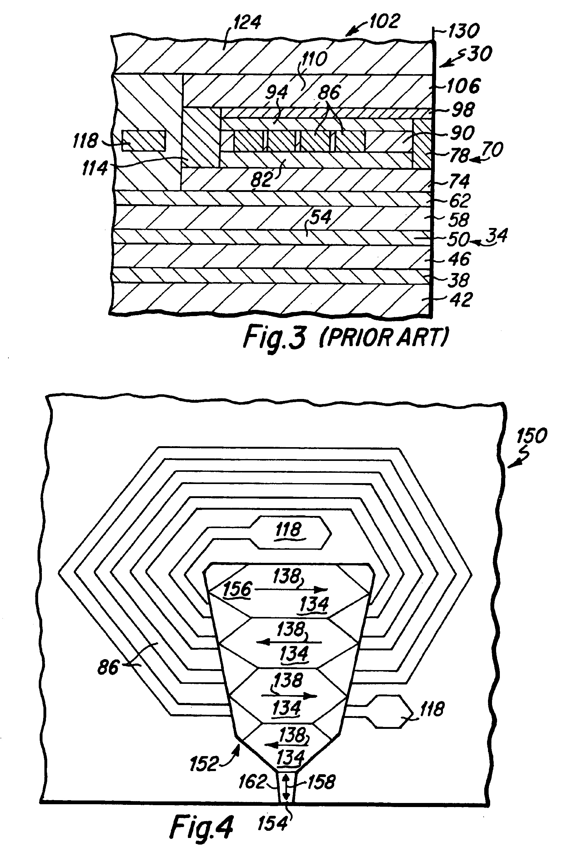
[0036]the present invention is depicted in FIGS. 5 and 6, wherein FIG. 5 is a top plan view depicting components of the write head portion of a magnetic head 170 of the present invention that is suitable for use as the magnetic head 16 in the disk drive 10 depicted in FIG. 1, and FIG. 6 is a side cross-sectional view taken along lines 6—6 of FIG. 5. Initially, in comparing the head 170 depicted in FIG. 5 with that depicted in FIG. 4, it is to be noted that the second magnetic pole yoke 156 and pole tip 154 of the head 150 depicted in FIG. 4 is substantially identical to that utilized within the magnetic head 170 depicted in FIG. 5. Basically, the magnetic head 170 of the present invention, as depicted in FIGS. 5 and 6, includes a pole tip heating element 180 that is fabricated proximate the pole tip 154 to provide heat energy to the pole tip 154. It has been found that where the pole tip 154 is sufficiently heated, the permeability of the pole tip material is increased, pole tip str...
embodiment 220
[0039]A first alternative embodiment 220 of the present invention is depicted in FIG. 7, which is a top plan view that is similar to FIG. 5. The heater element 224 depicted in FIG. 7 is an augmentation of the heater element 180 depicted in FIG. 5, wherein an additional thickness of electrically conductive material 228 is deposited upon the electrical leads 190 and 198 of the heater element 180 depicted in FIG. 5. The additional electrically conductive metal portions 228 serve to reduce the electrical resistance of the electrical leads of the heater element 224, such that the significant electrical resistance of the heater element 224 is even more localized at the narrow heating portions 194 above the pole tip. This results in a more efficient heating of the pole tip of the magnetic head 220.
embodiment 250
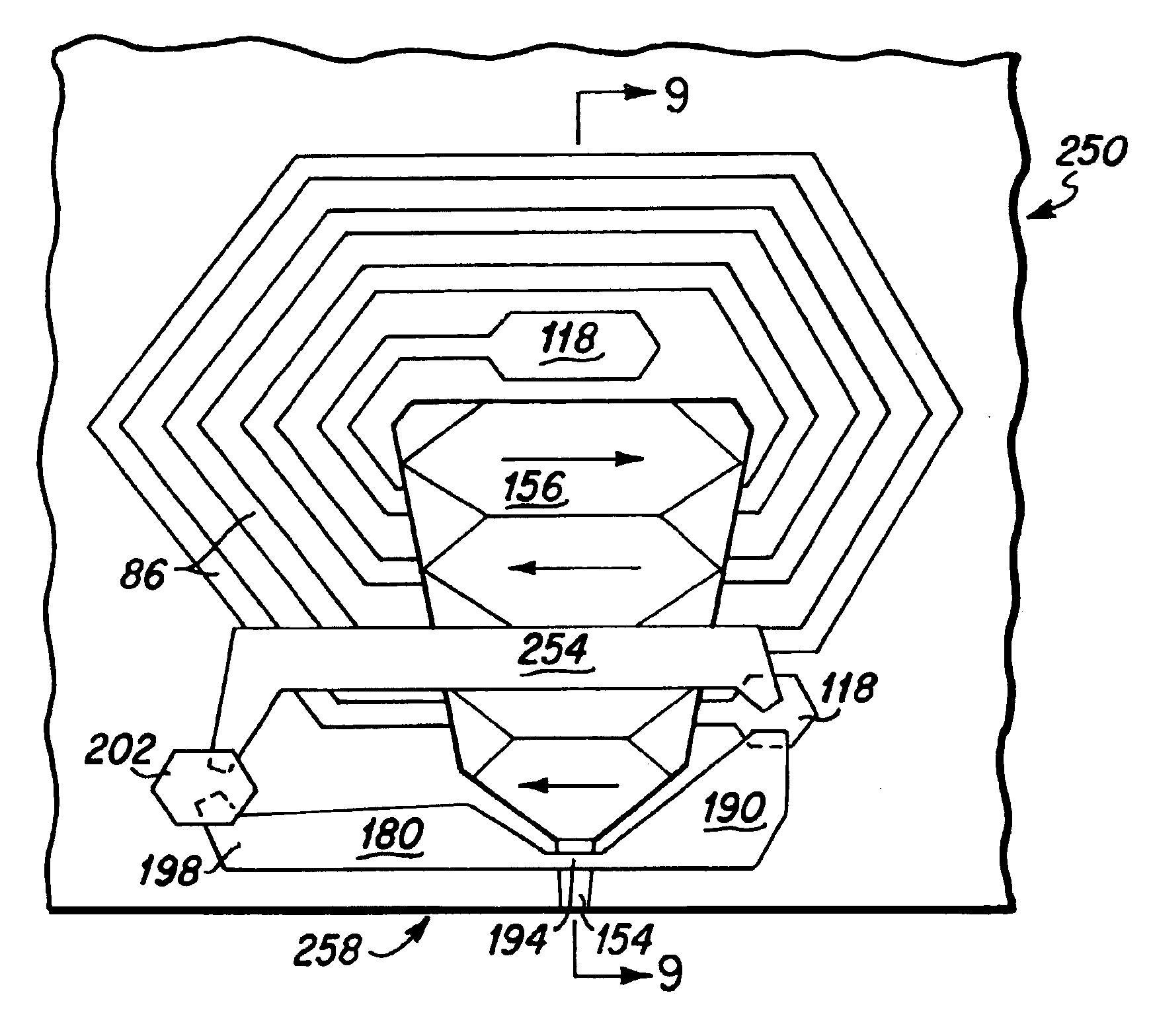
[0040]Another alternative embodiment 250 of the present invention is depicted in FIGS. 8 and 9, wherein FIG. 8 is a top plan view of the write head portion of the magnetic head 250, and FIG. 9 is a side cross-sectional view taken along lines 9—9 of FIG. 8. As depicted in FIGS. 8 and 9, and with reference to the embodiment of the present invention depicted in FIGS. 5 and 6, the significant difference between the embodiments 250 and 170 is the addition of a second electrically conductive leg 254 to the heating element 258 depicted in FIGS. 8 and 9. Basically, the additional leg 254 provides a second electrically conductive path. By controlling the width of the second leg 254, relative to the width of the heating element 194, the quantity of electrical current flowing through the heating element 194 is controlled, whereby the quantity of heat provided by the heating element 194 is likewise controlled. As can be seen in FIG. 9, both legs 180 and 254 of the heating element 258 are fabric...
PUM
| Property | Measurement | Unit |
|---|---|---|
| electrical resistance | aaaaa | aaaaa |
| width | aaaaa | aaaaa |
| resistance | aaaaa | aaaaa |
Abstract
Description
Claims
Application Information
 - R&D
- Intellectual Property
- Life Sciences
- Materials
- Tech Scout
- Unparalleled Data Quality
- Higher Quality Content
- 60% Fewer Hallucinations
Browse by: Latest US Patents, China's latest patents, Technical Efficacy Thesaurus, Application Domain, Technology Topic, Popular Technical Reports.
© 2025 PatSnap. All rights reserved.Legal|Privacy policy|Modern Slavery Act Transparency Statement|Sitemap|About US| Contact US: help@patsnap.com


