X-ray fluorescence system with apertured mask for analyzing patterned surfaces

a fluorescence system and patterned surface technology, applied in the field of analytical instruments, can solve the problems of vacancies destabilizing atoms, difficult to narrow an x-ray beam to such widths, and extremely small feature sizes in chip regions of the ic that are difficult to measure directly with xr

Inactive Publication Date: 2006-04-04
X-RAY OPTICAL SYSTEM INC
View PDF16 Cites 38 Cited by
  • Summary
  • Abstract
  • Description
  • Claims
  • Application Information

AI Technical Summary

Benefits of technology

[0013]An additional optical element can be used for controlling the excitation radiation from the source, through the elongate aperture, and toward the two-dimensional sample area of the IC. An optical element can also be used for directing the emissions from the aperture to the detector. The optical element can be, for example, a monocapillary element, a polycapillary element, a curved crystal element, a multi-layer element, a pin-hole element or a slot element. The optical element may provide beam gain and beam control.

Problems solved by technology

As discussed further below, certain challenges exist in applying XRF techniques to patterned surfaces having many, closely spaced heterogeneous materials—for example, semiconductor integrated circuits (ICs), flat panel displays, surface acoustic wave (SAW) devices, printed circuit boards, planar lightwave circuits, etc.
During IC fabrication, many complicated processes are used to deposit and pattern many differing materials on a wafer.
However, the extremely small feature sizes in chip regions of the IC are difficult to measure directly with XRF.
As the excitation photons strike the sample, they knock electrons out of their orbits around the nuclei of the atoms in the sample, creating vacancies that destabilize the atoms.
Flux directed toward other lines, and the resultant fluorescence emitted from those lines, may confuse the results.
It is difficult to narrow an x-ray beam to such widths, without stimulating other adjacent regions and confusing the XRF results.
However, this technique assumes that measurements made on the test wafer will “predict” the dimensions of the film deposited over the final wafer.
Moreover, this technique incurs the time and expense of processing an extra test wafer.

Method used


Image

  • X-ray fluorescence system with apertured mask for analyzing patterned surfaces
  • X-ray fluorescence system with apertured mask for analyzing patterned surfaces
  • X-ray fluorescence system with apertured mask for analyzing patterned surfaces

Examples


Embodiment Construction

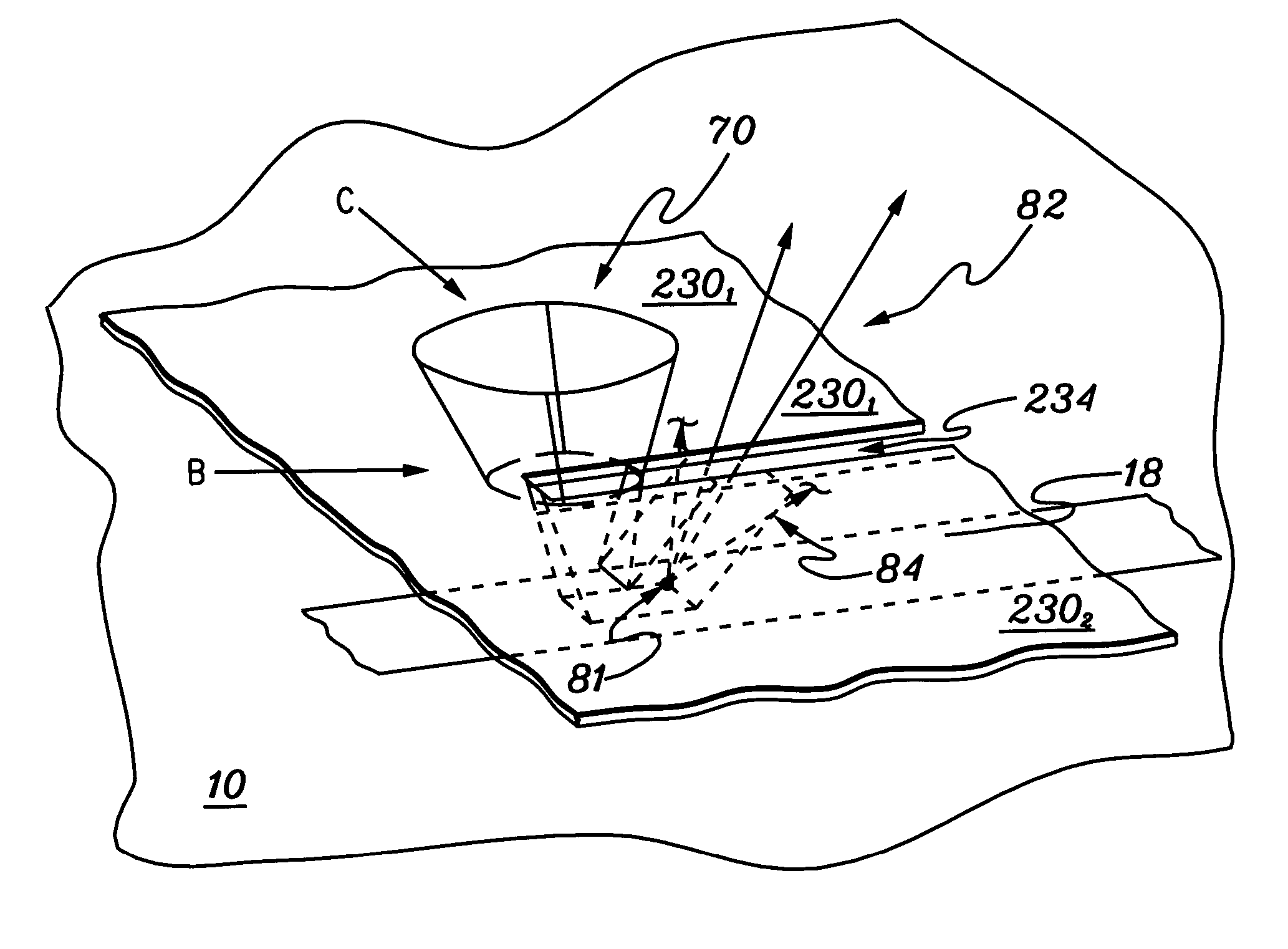
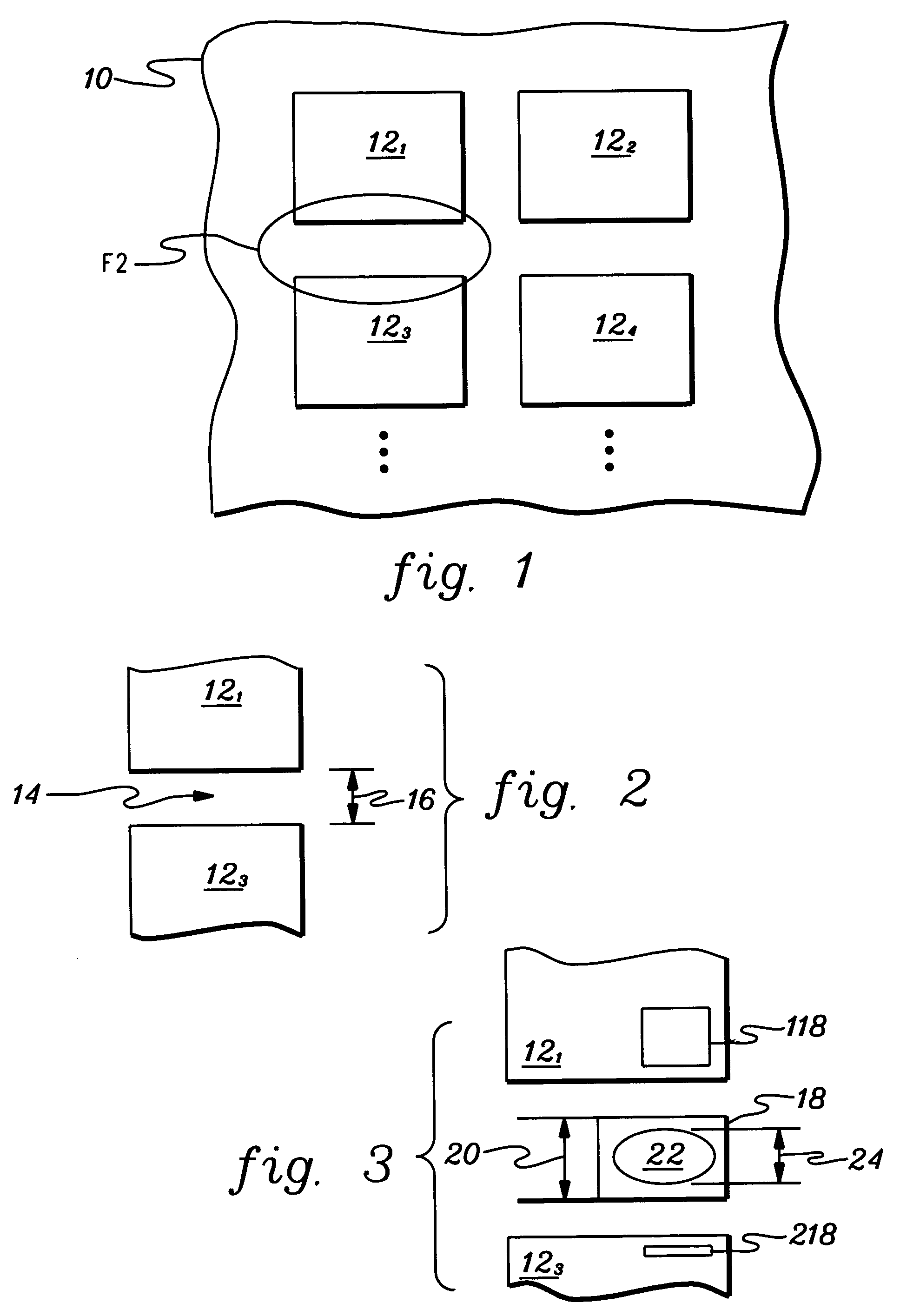
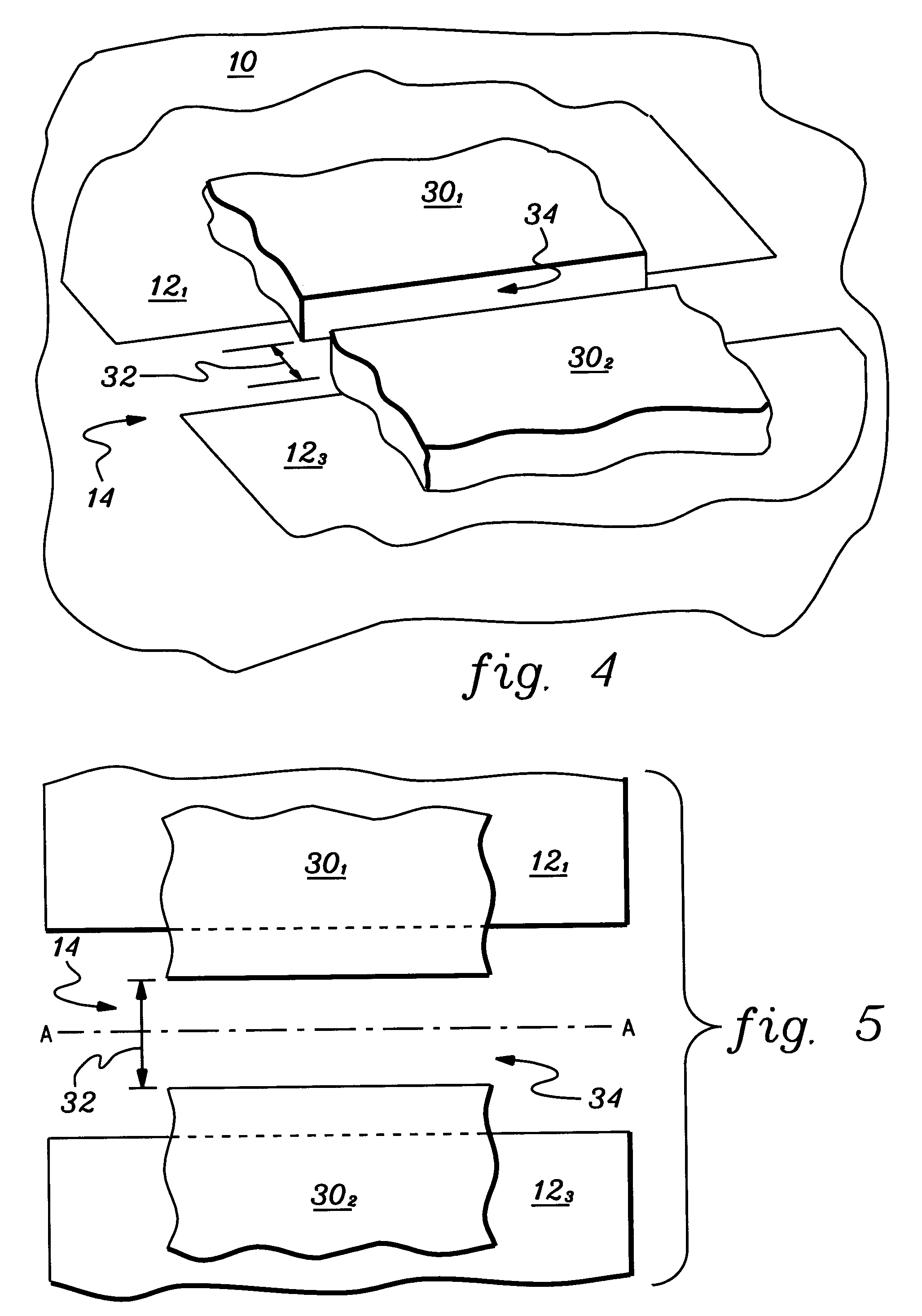
[0027]An apparatus and associated analytical techniques are disclosed for effectively analyzing certain regions of patterned surfaces, while preventing other areas of the surface and undesireable beam scattering from negatively impacting the results. This technique is especially useful for analyzing test regions in the scribe lines between chip regions of an integrated circuit, using x-ray or other related equipment having certain minimal space and sample area requirements.

[0028]As discussed above, the small feature sizes currently forming patterned surfaces such as semiconductor ICs present certain analysis challenges. X-ray fluorescence (XRF), x-ray diffraction (XRD), and x-ray reflectivity (XRR) systems involve the use of radiation sources, optics, detectors which can be difficult to accurately place over sub-micron sample areas. Moreover, the excitation beam spot sizes, though dramatically improved to the 10 micron range in the last few years, are still larger than the IC featur...


PUM

PropertyMeasurementUnit
sizesaaaaaaaaaa
widthaaaaaaaaaa
sizeaaaaaaaaaa

Abstract

Measurement technique and apparatus for examining a region of a patterned surface such as an integrated circuit (IC). Excitation x-ray, neutron, particle-beam or gamma ray radiation is directed toward a two-dimensional sample area of the IC. Emissions (e.g., x-ray fluorescence—XRF) from the sample area are detected. A mask is placed in a planar radiation path formed by the source, detector and the sample area, and in one embodiment moveable relative to the sample area. The mask includes an elongate aperture to substantially confine the excitation radiation directed to the sample area, and the emissions from the sample area, to the planar radiation path when arranged parallel to a first axis of the two-dimensional sample area. The invention allows predictive measurement of feature characteristics in active circuit regions of the IC, using sample areas outside of these regions.

Description

GOVERNMENT RIGHTS STATEMENT[0001]This invention was made with Government support under Contract #: DMI-0091570 awarded by the National Science Foundation to X-Ray Optical Systems, Inc. The Government has certain rights in this invention.TECHNICAL FIELD[0002]The present invention relates to analytical instruments. More particularly, the present invention relates to an apparatus and technique for controlling an x-ray beam exciting a sample, and the resultant fluorescence emitted from the sample, to improve analysis results. The invention is particularly suited to x-ray fluorescence (XRF) measurement of patterned surfaces such as small regions of materials forming semiconductor integrated circuits.BACKGROUND OF THE INVENTION[0003]X-ray fluorescence (XRF) analysis is universally recognized as a very accurate method of measuring the atomic composition and other characteristics of a sample material. This technique (and its close relatives) involve irradiating a sample area with high energ...

Claims


Application Information

Patent Timeline
Patent Type & Authority Patents(United States)
IPC IPC(8): G01N23/223G01N23/20H01L21/66
CPCG01N23/223G01N2223/076
Inventor CHEN, ZEWUTERADA, SHINICHI
Owner X-RAY OPTICAL SYSTEM INC
Why Eureka
Try Eureka